

Microcomputer Circuits and Processes
Microcomputer Circuits and Processes
Microcomputer Circuits and Processes

Create successful ePaper yourself
Turn your PDF publications into a flip-book with our unique Google optimized e-Paper software.
16 rnA<br />
R<br />
8 rnA<br />
2R<br />
2R<br />
2R<br />
2R<br />
R<br />
S,<br />
R<br />
current-to-voltage<br />
converter<br />
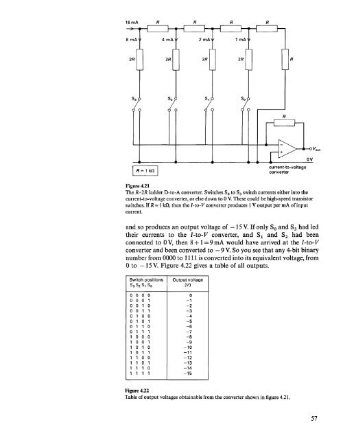
Figure 4.21<br />
The R-2R ladder D-to-A converter. Switches So to S3 switch currents either into the<br />
current-to-voltage converter, or else down to 0 V.These could be high-speed transistor<br />
switches. If R= 1kn, then the I-to-V converter produces 1V output per rnA of input<br />
current.<br />
<strong>and</strong> so produces an output voltage of -15 V. If only So <strong>and</strong> S3 had led<br />
their currents to the I-to- V converter, <strong>and</strong> S1 <strong>and</strong> S2 had been<br />
connected to 0 V, then 8+ 1= 9 rnA would have arrived at the I-to- V<br />
converter <strong>and</strong> been converted to - 9 V. So you see that any 4-bit binary<br />
number from 0000 to 1111is converted into its equivalent voltage, from<br />
o to -15 V. Figure 4.22 gives a table of all outputs.<br />
Switch positions Output voltage<br />
S3 S2 S, So<br />
(V)<br />
0 0 0 0 0<br />
0 0 0 1 -1<br />
0 0 1 0 -2<br />
0 0 1 1 -3<br />
0 1 0 0 -4<br />
0 1 0 1 -5<br />
0 1 1 0 -6<br />
0 1 1 1 -7<br />
1 0 0 0 -8<br />
1 0 0 1 -9<br />
1 0 1 0 -10<br />
1 0 1 1 -11<br />
1 i 0 0 -12<br />
1 1 0 1 -13<br />
1 1 1 0 -14<br />
1 1 1 1 -15<br />
Figure 4.22<br />
Table of output voltages obtainable from the converter shown in figure 4.21.<br />
57


