Microcomputer Circuits and Processes
Microcomputer Circuits and Processes
Microcomputer Circuits and Processes
You also want an ePaper? Increase the reach of your titles
YUMPU automatically turns print PDFs into web optimized ePapers that Google loves.
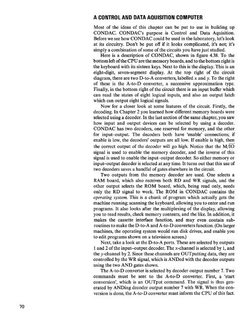
A CONTROL AND DATA AQUISITION<br />
COMPUTER<br />
Most of the ideas of this chapter can be put to use in building up<br />
CONDAC. CONDAC's purpose is Control <strong>and</strong> Data Aquisition.<br />
Before we see how CONDAC could be used in the laboratory, let's look<br />
at its circuitry. Don't be put off if it looks complicated, it's not; it's<br />
simply a combination of some of the circuits you have just studied.<br />
Here is a description of CONDAC, shown in figure 4.38. To the<br />
bottom left of the CPU are the memory boards, <strong>and</strong> to the bottom right is<br />
the keyboard with its sixteen keys. Next to this is the display. This is an<br />
eight-digit, seven-segment display. At the top right of the circuit<br />
diagram, there are two D-to-A converters, labelled x <strong>and</strong> y. To the right<br />
of these is the A-to-D converter, a successive approximation type.<br />
Finally, in the bottom right of the circuit there is an input buffer which<br />
can read the states of eight logical inputs, <strong>and</strong> also an output latch<br />
which can output eight logical signals.<br />
Now for a closer look at some features of the circuit. Firstly, the<br />
decoding. In Chapter 2 you learned how different memory boards were<br />
selected using a decoder. In the last section of the same chapter, you saw<br />
how input <strong>and</strong> output devices can be selected by using a decoder.<br />
CONDAC has two decoders, one reserved for memory, <strong>and</strong> the other<br />
for input-output. The decoders both have 'enable' connections; if<br />
enable is low, the decoders' outputs are all low. If enable is high, then<br />
the correct output of the decoder will go high. Notice that the MilO<br />
signal is used to enable the memory decoder, <strong>and</strong> the inverse of this<br />
signal is used to enable the input-output decoder. So either memory or<br />
input-output decoder is selected at any time. It turns out that this use of<br />
two decoders saves a h<strong>and</strong>ful of gates elsewhere in the circuit.<br />
Two outputs from the memory decoder are used. One selects a<br />
RAM board, which also receives both RD <strong>and</strong> WR signals, <strong>and</strong> the<br />
other output selects the ROM board, which, being read only, needs<br />
only the RD signal to work. The ROM in CONDAC contains the<br />
operating system. This is a chunk of program which actually gets the<br />
machine running; scanning the keyboard, allowing you to enter <strong>and</strong> run<br />
programs. It also looks after the multiplexing of the display, allowing<br />
you to read results, check memory contents, <strong>and</strong> the like. In addition, it<br />
makes the cassette interface function, <strong>and</strong> may even contain subroutines<br />
to make the D-to-A <strong>and</strong> A-to-D converters function. (On larger<br />
machines, the operating system would run disk drives, <strong>and</strong> enable you<br />
to edit programs shown on a television screen.)<br />
Next, take a look at the D-to-A ports. These are selected by outputs<br />
1 <strong>and</strong> 2 of the input-output decoder. The x-channel is selected by 1,<strong>and</strong><br />
the y-channel by 2. Since these channels are OUTputting data, they are<br />
controlled by the WR signal, which is ANDed with the decoder outputs<br />
using the two AND gates shown.<br />
The A-to-D converter is selected by decoder output number 7. Two<br />
comm<strong>and</strong>s must be sent to the A-to-D converter. First, a 'start<br />
conversion', which is an OUTput comm<strong>and</strong>. The signal is thus generated<br />
by ANDing decoder output number 7 with WR. When the conversion<br />
is done, the A-to-D converter must inform the CPU of this fact.<br />
70


