WEIGH SCALE BLENDER® - Maguire Products
WEIGH SCALE BLENDER® - Maguire Products
WEIGH SCALE BLENDER® - Maguire Products

Create successful ePaper yourself
Turn your PDF publications into a flip-book with our unique Google optimized e-Paper software.
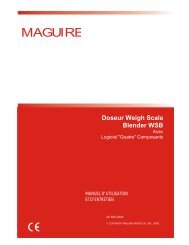
<strong>WEIGH</strong> <strong>SCALE</strong> <strong>BLENDER®</strong><br />
MAGUIRE PRODUCTS, INC.<br />
Controller: Controls and Outputs<br />
1. POWER ON switch<br />
Controls all power to the controller and all outputs. When power is switched off, battery backed-up RAM preserves all<br />
internal totals and parameters. All other functions are reset for normal start-up when power is restored.<br />
2. STOP END OF CYCLE / CONTINUE switch<br />
This is the switch that you should use to STOP the system. This switch is wired in series with the level sensor.<br />
Turning it off breaks the signal to the computer the same as covering the level sensor with material. This stops the<br />
process at the end of a full cycle.<br />
3. IMMEDIATE PAUSE / CONTINUE switch<br />
Causes a computer-controlled immediate pause during a cycle. Dispenses will stop in mid-dispense if necessary.<br />
When switched back to CONTINUE, the process continues without any error in amounts dispensed.<br />
4. ALL AIR SOLENOID outputs<br />
There is a single 8 pin or 14 pin (or 17 pin) Amphanol plug located on the front of the control panel. this provides<br />
output of all 120 volt (or 24 volt) signals to drive the air solenoids. These power sources are transistor driven and are<br />
protected by the 1/2 amp panel fuse. See the wiring diagram section for the correct wiring to each pin.<br />
If more then 7 outputs are to be driven, a 14 pin connector is provided with outputs for components 8, 9, A, B, and C.<br />
If 24-volt solenoids are used, a 17 pin connector is provided.<br />
5. POWER OUTPUTS (receptacles on panel front)<br />
Each outlet puts out 120 volts (240 outside USA) through internal plug- in solid state relays rated and fused at 3<br />
amps. These relay outputs are designed to drive motors or other devices requiring power up to 3 amps each. The<br />
LEFT outlet is for component number 5, and the RIGHT outlet is for component number 6.<br />
6. EIGHT CHARACTER DISPLAY<br />
Displays the accumulated total bin weight, in grams, after each dispense. The display flashes when an inadequate<br />
dispense has occurred and the dispense is going to be retried. Other information displayed here includes material<br />
usage totals, internal parameters, component types and settings and various information prompts to assist the<br />
operator.<br />
###### Numbers displayed are the total weight of material, in grams, in the bin at any time. The weight in<br />
the bin is updated only after an individual dispense is complete. During the dispense the displayed<br />
weight does not change.<br />
P<br />
M<br />
In the left most position indicates unit is in PROGRAM mode.<br />
Indicates unit is in MANUAL mode.<br />
1 R 20.0 Indicates: Component 1, REGRIND, and SETTING of 20 percent.<br />
INVALID Indicates: 1. You pressed an incorrect key - or<br />
2. You pressed a key for a function that is not active - or<br />
3. You are not in the right mode for this key to operate.<br />
PASSWORD<br />
INSTR --<br />
Password is displayed when you press the "*" key from the normal mode.<br />
Enter "11111" for MANUAL mode or "22222" for PROGRAM mode - or<br />
Enter your own password number if you have established one.<br />
This is displayed when you press the "*" key from the PROGRAM mode.<br />
Enter a 2-digit instruction number for special tasks.<br />
SETTING, OPERATE, TIMED, and CALIBRATE are displayed when the respective keys are pressed from the manual or<br />
program modes. These displays are followed by pressing a device key; 1 through 9, A, B, C, DUMP, ALARM, MIX, or HOLD.<br />
The word FLASHING on the display means that retries are occurring because the first dispense was not enough. Other error<br />
conditions also cause flashing.<br />
Edition: March 24, 2008 32