WEIGH SCALE BLENDER® - Maguire Products
WEIGH SCALE BLENDER® - Maguire Products
WEIGH SCALE BLENDER® - Maguire Products

Create successful ePaper yourself
Turn your PDF publications into a flip-book with our unique Google optimized e-Paper software.
<strong>WEIGH</strong> <strong>SCALE</strong> <strong>BLENDER®</strong><br />
MAGUIRE PRODUCTS, INC.<br />
ROM OK/ROM BAD indicates the condition of ROM chip. See KEYPAD, *25, for explanation.<br />
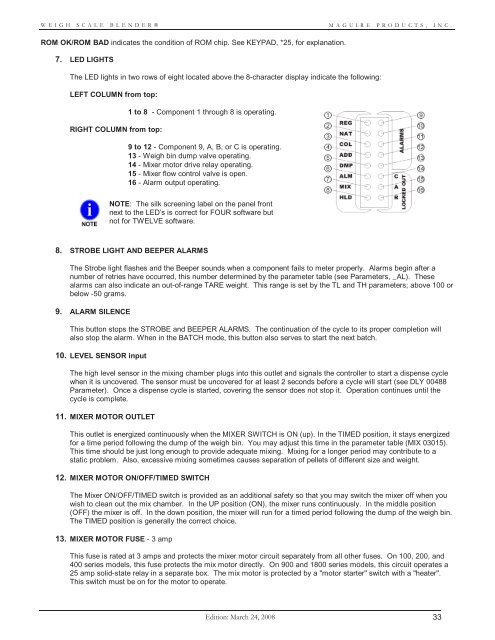
7. LED LIGHTS<br />
The LED lights in two rows of eight located above the 8-character display indicate the following:<br />
LEFT COLUMN from top:<br />
RIGHT COLUMN from top:<br />
1 to 8 - Component 1 through 8 is operating.<br />
9 to 12 - Component 9, A, B, or C is operating.<br />
13 - Weigh bin dump valve operating.<br />
14 - Mixer motor drive relay operating.<br />
15 - Mixer flow control valve is open.<br />
16 - Alarm output operating.<br />
NOTE: The silk screening label on the panel front<br />
next to the LED’s is correct for FOUR software but<br />
not for TWELVE software.<br />
8. STROBE LIGHT AND BEEPER ALARMS<br />
The Strobe light flashes and the Beeper sounds when a component fails to meter properly. Alarms begin after a<br />
number of retries have occurred, this number determined by the parameter table (see Parameters, _AL). These<br />
alarms can also indicate an out-of-range TARE weight. This range is set by the TL and TH parameters; above 100 or<br />
below -50 grams.<br />
9. ALARM SILENCE<br />
This button stops the STROBE and BEEPER ALARMS. The continuation of the cycle to its proper completion will<br />
also stop the alarm. When in the BATCH mode, this button also serves to start the next batch.<br />
10. LEVEL SENSOR input<br />
The high level sensor in the mixing chamber plugs into this outlet and signals the controller to start a dispense cycle<br />
when it is uncovered. The sensor must be uncovered for at least 2 seconds before a cycle will start (see DLY 00488<br />
Parameter). Once a dispense cycle is started, covering the sensor does not stop it. Operation continues until the<br />
cycle is complete.<br />
11. MIXER MOTOR OUTLET<br />
This outlet is energized continuously when the MIXER SWITCH is ON (up). In the TIMED position, it stays energized<br />
for a time period following the dump of the weigh bin. You may adjust this time in the parameter table (MIX 03015).<br />
This time should be just long enough to provide adequate mixing. Mixing for a longer period may contribute to a<br />
static problem. Also, excessive mixing sometimes causes separation of pellets of different size and weight.<br />
12. MIXER MOTOR ON/OFF/TIMED SWITCH<br />
The Mixer ON/OFF/TIMED switch is provided as an additional safety so that you may switch the mixer off when you<br />
wish to clean out the mix chamber. In the UP position (ON), the mixer runs continuously. In the middle position<br />
(OFF) the mixer is off. In the down position, the mixer will run for a timed period following the dump of the weigh bin.<br />
The TIMED position is generally the correct choice.<br />
13. MIXER MOTOR FUSE - 3 amp<br />
This fuse is rated at 3 amps and protects the mixer motor circuit separately from all other fuses. On 100, 200, and<br />
400 series models, this fuse protects the mix motor directly. On 900 and 1800 series models, this circuit operates a<br />
25 amp solid-state relay in a separate box. The mix motor is protected by a "motor starter" switch with a "heater".<br />
This switch must be on for the motor to operate.<br />
Edition: March 24, 2008 33