User Manual - Terasic
User Manual - Terasic
User Manual - Terasic
SHOW LESS
- No tags were found...

Create successful ePaper yourself
Turn your PDF publications into a flip-book with our unique Google optimized e-Paper software.
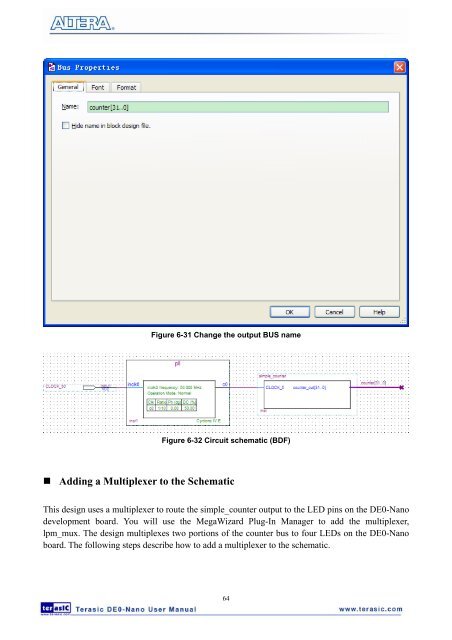
Figure 6-31 Change the output BUS nameFigure 6-32 Circuit schematic (BDF)• Adding a Multiplexer to the SchematicThis design uses a multiplexer to route the simple_counter output to the LED pins on the DE0-Nanodevelopment board. You will use the MegaWizard Plug-In Manager to add the multiplexer,lpm_mux. The design multiplexes two portions of the counter bus to four LEDs on the DE0-Nanoboard. The following steps describe how to add a multiplexer to the schematic.64