User Manual - Terasic
User Manual - Terasic
User Manual - Terasic
- No tags were found...

Create successful ePaper yourself
Turn your PDF publications into a flip-book with our unique Google optimized e-Paper software.
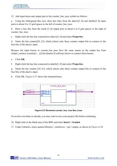
15. Add input buses and output pins to the counter_bus_mux symbol as follows:a. Using the Orthogonal Bus tool, draw bus lines from the data1x[3..0] and data0x[3..0] inputports to about 8 to 12 grid spaces to the left of counter_bus_mux.b. Draw a bus line from the result [3..0] output port to about 6 to 8 grid spaces to the right ofcounter_bus_mux.c. Right-click the bus line connected to data1x[3..0] and select Properties.d. Name the bus counter[26..23], which selects only those counter output bits to connect to thefour bits of the data1x input.Because the input busses to counter_bus_mux have the same names as the output bus fromsimple_counter, (counter[x .. y]) the Quartus II software knows to connect these busses.e. Click OK.f. Right-click the bus line connected to data0x[3..0] and select Properties.g. Name the bus counter [24..21], which selects only those counter output bits to connect to thefour bits of the data1x input.h. Click OK. Figure 6-37 shows the renamed buses.Figure 6-37 Renamed counter_bus_mux Bus LinesIf you have not done so already, you may want to save your project file before continuing.16. Right click in the blank area of the BDF and select Insert > Symbol.17. Under Libraries, select quartus/libraries > primitives > pin >output, as shown in Figure 6-38.68