User Manual - Terasic
User Manual - Terasic
User Manual - Terasic
- No tags were found...

Create successful ePaper yourself
Turn your PDF publications into a flip-book with our unique Google optimized e-Paper software.
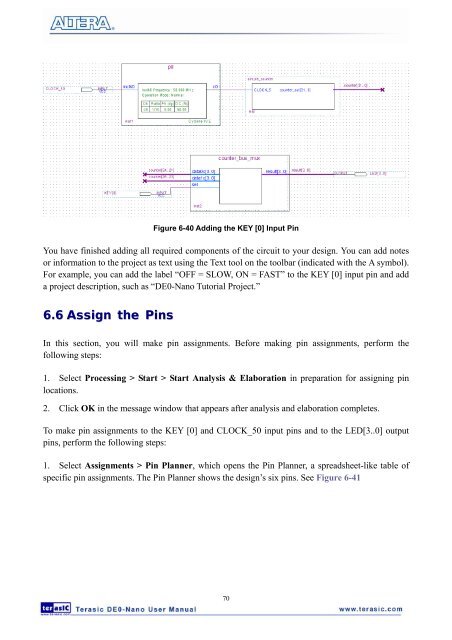
Figure 6-40 Adding the KEY [0] Input PinYou have finished adding all required components of the circuit to your design. You can add notesor information to the project as text using the Text tool on the toolbar (indicated with the A symbol).For example, you can add the label “OFF = SLOW, ON = FAST” to the KEY [0] input pin and adda project description, such as “DE0-Nano Tutorial Project.”6.6 Assign the PinsIn this section, you will make pin assignments. Before making pin assignments, perform thefollowing steps:1. Select Processing > Start > Start Analysis & Elaboration in preparation for assigning pinlocations.2. Click OK in the message window that appears after analysis and elaboration completes.To make pin assignments to the KEY [0] and CLOCK_50 input pins and to the LED[3..0] outputpins, perform the following steps:1. Select Assignments > Pin Planner, which opens the Pin Planner, a spreadsheet-like table ofspecific pin assignments. The Pin Planner shows the design’s six pins. See Figure 6-4170