- Page 2 and 3: LightWave ® 10Reference ManualLice
- Page 4: AcknowledgementsEngineering:Chuck B
- Page 7 and 8: VIContentsLightWave 10Copyright and
- Page 9 and 10: VIIILightWave 10Optimizing RAM Usag
- Page 11 and 12: XLightWave 10Chapter 5: Multiply Ta
- Page 13 and 14: XIILightWave 10
- Page 16 and 17: Chapter 1: LightWave 3D Getting Sta
- Page 18 and 19: Chapter 1: LightWave 3D Getting Sta
- Page 20 and 21: Key LightWave Terms and ConceptsIn
- Page 22 and 23: LightWave Panelsand DialogsLightWav
- Page 24 and 25: Customizing Your InterfaceChapter 1
- Page 26 and 27: Customizing Keyboard ShortcutsChapt
- Page 28 and 29: Chapter 1: LightWave 3D Getting Sta
- Page 30 and 31: Images and MemoryMipmapping is a pr
- Page 32 and 33: PropertiesChapter 1: LightWave 3D G
- Page 34: Volume iModelerChapter 2: Introduct
- Page 37 and 38: 24LightWave 10 - ModelerIntroductio
- Page 39 and 40: 26Point SelectionLightWave 10 - Mod
- Page 41 and 42: 28LightWave 10 - ModelerPolygon Sel
- Page 43: 30InterfaceLightWave 10 - ModelerMo
- Page 47 and 48: 34LightWave 10 - ModelerPolyLines (
- Page 49 and 50: 36Closing Object FilesLightWave 10
- Page 51 and 52: 38LightWave 10 - ModelerMaintaining
- Page 53 and 54: 40Curve DivisionsLightWave 10 - Mod
- Page 55 and 56: 42LightWave 10 - ModelerDisplay Opt
- Page 57 and 58: 44Show Polygon SelectionLightWave 1
- Page 59 and 60: 46LightWave 10 - ModelerHidden Line
- Page 61: 48Independent OptionsLightWave 10 -
- Page 64 and 65: Units TabChapter 2: Introduction to
- Page 66 and 67: Chapter 2: Introduction to Modeling
- Page 68 and 69: Chapter 2: Introduction to Modeling
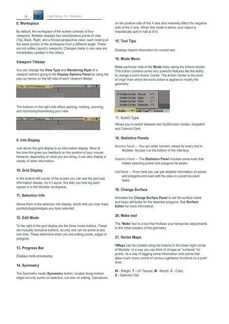
- Page 70 and 71: Bottom Edge MenuInfo DisplayJust ab
- Page 72 and 73: Diffuse — Diffuse (sometimes call
- Page 74 and 75: Chapter 3: Create TabChapter 3: Cre
- Page 79 and 80: 66LightWave 10 - ModelerNumeric Pan
- Page 81 and 82: 68Cone ToolLightWave 10 - ModelerSt
- Page 83 and 84: 70LightWave 10 - ModelerAxis — Th
- Page 85 and 86: 72LightWave 10 - ModelerHINT: The B
- Page 87 and 88: 74LightWave 10 - ModelerWedge ToolT
- Page 89 and 90: 76LightWave 10 - ModelerThis entire
- Page 91 and 92: 78Gemstone ToolLightWave 10 - Model
- Page 93 and 94: 80LightWave 10 - ModelerThe Paramet
- Page 95 and 96:
82StarSphere ToolLightWave 10 - Mod
- Page 97 and 98:
84The Text Numeric PanelLightWave 1
- Page 99 and 100:
86LightWave 10 - ModelerLogoThe Log
- Page 101 and 102:
88LightWave 10 - Modelerletters in
- Page 103 and 104:
90LightWave 10 - ModelerStippleThe
- Page 105 and 106:
92LightWave 10 - ModelerThe Add Poi
- Page 107 and 108:
94LightWave 10 - ModelerStep 4: If
- Page 109 and 110:
96Make Triangle FanLightWave 10 - M
- Page 111 and 112:
98LightWave 10 - ModelerStep 2: Ope
- Page 113 and 114:
100LightWave 10 - ModelerStep 2: Yo
- Page 115 and 116:
102LightWave 10 - ModelerUsing Mode
- Page 117 and 118:
104LightWave 10 - Modeler
- Page 119 and 120:
106Modify TabLightWave 10 - Modeler
- Page 121 and 122:
108To set the influence area:LightW
- Page 123 and 124:
110Center Data(default keyboard sho
- Page 125 and 126:
112Move PlusLightWave 10 - ModelerT
- Page 127 and 128:
114Snap Drag Tool(default keyboard
- Page 129 and 130:
116Point Normal MoveLightWave 10 -
- Page 131 and 132:
118LightWave 10 - ModelerAngle —
- Page 133 and 134:
120Vortex ToolLightWave 10 - Modele
- Page 135 and 136:
122Rotate Arbitrary AxisLightWave 1
- Page 137 and 138:
124TransformStretch Tool(default ke
- Page 139 and 140:
126LightWave 10 - ModelerTaper Tool
- Page 141 and 142:
128Jitter Command(default keyboard
- Page 143 and 144:
130Pole Evenly ToolLightWave 10 - M
- Page 145 and 146:
132Spline Guide ToolLightWave 10 -
- Page 147 and 148:
134Smooth ScalingLightWave 10 - Mod
- Page 149 and 150:
136SpherizeLightWave 10 - ModelerWr
- Page 151 and 152:
138LightWave 10 - Modeler
- Page 153 and 154:
140Multiply TabLightWave 10 - Model
- Page 155 and 156:
142LightWave 10 - ModelerNOTE: Some
- Page 157 and 158:
144LightWave 10 - ModelerThe Rounde
- Page 159 and 160:
146LightWave 10 - ModelerPresets Ta
- Page 161 and 162:
148Lathe Tool(default keyboard shor
- Page 163 and 164:
150Multishift ToolLightWave 10 - Mo
- Page 165 and 166:
152Extender Plus(default keyboard s
- Page 167 and 168:
154Extender ToolLightWave 10 - Mode
- Page 169 and 170:
156LightWave 10 - ModelerDelete Pat
- Page 171 and 172:
158LightWave 10 - ModelerNOTE: The
- Page 173 and 174:
160LightWave 10 - ModelerMotion Pat
- Page 175 and 176:
162LightWave 10 - ModelerStep 3: Pr
- Page 177 and 178:
164Morph Polygons ToolLightWave 10
- Page 179 and 180:
166Mirror XYZ ToolsLightWave 10 - M
- Page 181 and 182:
168LightWave 10 - Modelerwill get p
- Page 183 and 184:
170LightWave 10 - ModelerMotion Pat
- Page 185 and 186:
172LightWave 10 - ModelerOriented d
- Page 187 and 188:
174Radial Array ToolLightWave 10 -
- Page 189 and 190:
176Subdivide(default keyboard short
- Page 191 and 192:
178Band Saw Pro ToolLightWave 10 -
- Page 193 and 194:
180Split Polygons Tool(default keyb
- Page 195 and 196:
182LightWave 10 - ModelerBy default
- Page 197 and 198:
184LightWave 10 - ModelerThe Select
- Page 199 and 200:
186Fractalize ToolLightWave 10 - Mo
- Page 201 and 202:
188LightWave 10 - ModelerFast Tripl
- Page 203 and 204:
190Construct TabLightWave 10 - Mode
- Page 205 and 206:
192LightWave 10 - Modelerthe object
- Page 207 and 208:
194LightWave 10 - ModelerRemove Pol
- Page 209 and 210:
196UnionLightWave 10 - ModelerInter
- Page 211 and 212:
198LightWave 10 - ModelerTo use the
- Page 213 and 214:
200LightWave 10 - ModelerBoth Drill
- Page 215 and 216:
202LightWave 10 - ModelerPatchesPat
- Page 217 and 218:
204LightWave 10 - ModelerTo change
- Page 219 and 220:
206Convert MetaedgesLightWave 10 -
- Page 221 and 222:
208Detail TabLightWave 10 - Modeler
- Page 223 and 224:
210Set ValueLightWave 10 - ModelerW
- Page 225 and 226:
212Spin QuadsLightWave 10 - Modeler
- Page 227 and 228:
214Fix PolesLightWave 10 - ModelerF
- Page 229 and 230:
216CurvesLightWave 10 - ModelerSmoo
- Page 231 and 232:
218LightWave 10 - ModelerStep 4: Pr
- Page 233 and 234:
220LightWave 10 - ModelerStep 5: On
- Page 235 and 236:
222Tri Strip ACTCLightWave 10 - Mod
- Page 237 and 238:
224Map TabIntroductionLightWave 10
- Page 239 and 240:
226The old seam problemLightWave 10
- Page 241 and 242:
228Color MapLightWave 10 - ModelerI
- Page 243 and 244:
230Airbrush and Morph MapsLightWave
- Page 245 and 246:
232MoreLightWave 10 - ModelerNormal
- Page 247 and 248:
234WeightsLightWave 10 - ModelerThi
- Page 249 and 250:
236LightWave 10 - Modelerreceive a
- Page 251 and 252:
238Point ColorLightWave 10 - Modele
- Page 253 and 254:
240Vertex PaintOverviewLightWave 10
- Page 255 and 256:
242LightWave 10 - ModelerFrontface
- Page 257 and 258:
244LightWave 10 - ModelerVertex Pai
- Page 259 and 260:
246LightWave 10 - ModelerKeyboard S
- Page 261 and 262:
248Point LightLightWave 10 - Modele
- Page 263 and 264:
250Vertex Color PaintingLightWave 1
- Page 265 and 266:
252LightWave 10 - ModelerCustomisin
- Page 267 and 268:
254LightWave 10 - ModelerWith the C
- Page 269 and 270:
256LightWave 10 - ModelerPasting We
- Page 271 and 272:
258LightWave 10 - Modelerare some a
- Page 273 and 274:
260LightWave 10 - ModelerClamping W
- Page 275 and 276:
262LightWave 10 - ModelerImport/Exp
- Page 277 and 278:
264Map TypesLightWave 10 - ModelerU
- Page 279 and 280:
266LightWave 10 - ModelerHowever, t
- Page 281 and 282:
268New UV MapLightWave 10 - Modeler
- Page 283 and 284:
270LightWave 10 - ModelerPanel, not
- Page 285 and 286:
272Point MapLightWave 10 - ModelerQ
- Page 287 and 288:
274LightWave 10 - ModelerType the n
- Page 289 and 290:
276LightWave 10 - ModelerGuess View
- Page 291 and 292:
278LightWave 10 - ModelerSpherical
- Page 293 and 294:
280MorphLightWave 10 - ModelerNew E
- Page 295 and 296:
282Create Joint MorphLightWave 10 -
- Page 297 and 298:
284LightWave 10 - Modeler
- Page 299 and 300:
286Setup TabLightWave 10 - ModelerN
- Page 301 and 302:
288Edit SkelegonsLightWave 10 - Mod
- Page 303 and 304:
290SelectionLightWave 10 - ModelerT
- Page 305 and 306:
292Layout ToolsLightWave 10 - Model
- Page 307 and 308:
294LightWave 10 - Modeler
- Page 309 and 310:
296Utilities TabCommandsEdit User C
- Page 311 and 312:
298LScriptLScriptLightWave 10 - Mod
- Page 313 and 314:
300LightWave 10 - Modeler
- Page 315 and 316:
302SelectionLightWave 10 - ModelerV
- Page 317 and 318:
304Expand Selection(default keyboar
- Page 319 and 320:
306MoreLightWave 10 - ModelerSelect
- Page 321 and 322:
308Selection SwitchLightWave 10 - M
- Page 323 and 324:
310LightWave 10 - ModelerSurface to
- Page 325 and 326:
312LightWave 10 - ModelerView TabVi
- Page 327 and 328:
314Fit All(default keyboard shortcu
- Page 329 and 330:
316LayersLightWave 10 - ModelerDele
- Page 331 and 332:
318Flatten LayersLightWave 10 - Mod
- Page 333 and 334:
320Select Connected(default keyboar
- Page 335 and 336:
322MapsLightWave 10 - ModelerThere
- Page 337 and 338:
324Select OutlineLightWave 10 - Mod
- Page 339 and 340:
326LightWave 10 - ModelerTo select
- Page 341 and 342:
328LightWave 10 - Modeler
- Page 343 and 344:
iiLightWave 10Glossary of 3D Terms1
- Page 345 and 346:
ivLightWave 10Baud — Bits per sec
- Page 347 and 348:
viLightWave 10Color Bleeding — Wh
- Page 349 and 350:
viiiLightWave 10DWG — AutoCAD nat
- Page 351 and 352:
xLightWave 10Greeblies — English
- Page 353 and 354:
xiiLightWave 10Line-of-Sight (LoS)
- Page 355 and 356:
xivLightWave 10Optical Light Effect
- Page 357 and 358:
xviLightWave 10Refraction Index —
- Page 359 and 360:
xviiiLightWave 10Subtractive Opacit
- Page 361 and 362:
xxLightWave 10
- Page 363 and 364:
DIILightWave 10Dangle 119, 123Defau
- Page 365 and 366:
IVLightWave 10Duplicate:Mirror 165D
- Page 367 and 368:
VILightWave 10TTaper Constrain 127,
- Page 369 and 370:
VIIILightWave 10
- Page 371:
XLightWave 10