- Page 1 and 2: PLC-5 DeviceNetScanner Module1771-S
- Page 3: European Communities (EC)Directive
- Page 6 and 7: P-2 About This User ManualContentsT
- Page 8 and 9: P-4 About This User ManualCommon Te
- Page 10 and 11: P-6 About This User ManualTerminolo
- Page 12 and 13: P-8 About This User ManualPublicati
- Page 14 and 15: Table of ContentsiiConfiguring theD
- Page 16 and 17: Table of ContentsivPublication 1771
- Page 18 and 19: 1-2 Before You BeginWhat Your 1771-
- Page 20 and 21: 1-4 Before You BeginThe 1771-SDN sc
- Page 22 and 23: 1-6 Before You BeginCommunicating w
- Page 24 and 25: 1-8 Before You BeginWhat 1771-SDN M
- Page 26 and 27: 1-10 Before You BeginThe configurat
- Page 28 and 29: 1-12 Before You BeginPublication 17
- Page 30 and 31: 2-2 Planning Your Configuration and
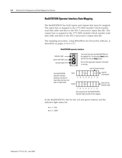
- Page 34 and 35: 2-6 Planning Your Configuration and
- Page 36 and 37: 2-8 Planning Your Configuration and
- Page 38 and 39: 2-10 Planning Your Configuration an
- Page 40 and 41: 3-2 Hardware SetupInstalling the PL
- Page 42 and 43: 3-4 Hardware SetupTo go online to t
- Page 44 and 45: 3-6 Hardware Setup3. Insert the int
- Page 46 and 47: 3-8 Hardware SetupSetting the Chann
- Page 48 and 49: 3-10 Hardware SetupConnecting the S
- Page 50 and 51: 3-12 Hardware SetupInstalling theSe
- Page 52 and 53: 3-14 Hardware SetupPublication 1771
- Page 54 and 55: 4-2 Configuring the DeviceNet Netwo
- Page 56 and 57: 4-4 Configuring the DeviceNet Netwo
- Page 58 and 59: 4-6 Configuring the DeviceNet Netwo
- Page 60 and 61: 4-8 Configuring the DeviceNet Netwo
- Page 62 and 63: 4-10 Configuring the DeviceNet Netw
- Page 64 and 65: 4-12 Configuring the DeviceNet Netw
- Page 66 and 67: 4-14 Configuring the DeviceNet Netw
- Page 68 and 69: 4-16 Configuring the DeviceNet Netw
- Page 70 and 71: 4-18 Configuring the DeviceNet Netw
- Page 72 and 73: 5-2 Communicating with DeviceNet fr
- Page 74 and 75: 5-4 Communicating with DeviceNet fr
- Page 76 and 77: 5-6 Communicating with DeviceNet fr
- Page 78 and 79: 5-8 Communicating with DeviceNet fr
- Page 80 and 81: 5-10 Communicating with DeviceNet f
- Page 82 and 83:
5-12 Communicating with DeviceNet f
- Page 84 and 85:
5-14 Communicating with DeviceNet f
- Page 86 and 87:
5-16 Communicating with DeviceNet f
- Page 88 and 89:
5-18 Communicating with DeviceNet f
- Page 90 and 91:
5-20 Communicating with DeviceNet f
- Page 92 and 93:
5-22 Communicating with DeviceNet f
- Page 94 and 95:
5-24 Communicating with DeviceNet f
- Page 96 and 97:
6-2 Creating and Running the Exampl
- Page 98 and 99:
6-4 Creating and Running the Exampl
- Page 100 and 101:
6-6 Creating and Running the Exampl
- Page 102 and 103:
6-8 Creating and Running the Exampl
- Page 104 and 105:
6-10 Creating and Running the Examp
- Page 106 and 107:
6-12 Creating and Running the Examp
- Page 108 and 109:
6-14 Creating and Running the Examp
- Page 110 and 111:
7-2 TroubleshootingNetwork Status I
- Page 112 and 113:
7-4 TroubleshootingNumericCodeDescr
- Page 114 and 115:
A-2 1785-ENET Module Channel Config
- Page 116 and 117:
B-2 Installing and Configuring the
- Page 118 and 119:
B-4 Installing and Configuring the
- Page 120 and 121:
C-2 Installing and Configuring the
- Page 122 and 123:
C-4 Installing and Configuring the
- Page 124 and 125:
D-2 Data Map ExampleExample Framewo
- Page 126 and 127:
D-4 Data Map ExampleIn 1-slot addre
- Page 128 and 129:
D-6 Data Map ExampleExample OutputM
- Page 130 and 131:
D-8 Data Map ExampleThe following i
- Page 132 and 133:
D-10 Data Map ExamplePublication 17
- Page 134 and 135:
2 Indexsetting the I/O chassis back
- Page 136:
( )Other CommentsPLEASE FOLD HERENO
- Page 139:
PLC-5 DeviceNet Scanner Module User