1771-6.5.132, PLC-5 DeviceNet Scanner User Manual
1771-6.5.132, PLC-5 DeviceNet Scanner User Manual
1771-6.5.132, PLC-5 DeviceNet Scanner User Manual
- No tags were found...

You also want an ePaper? Increase the reach of your titles
YUMPU automatically turns print PDFs into web optimized ePapers that Google loves.
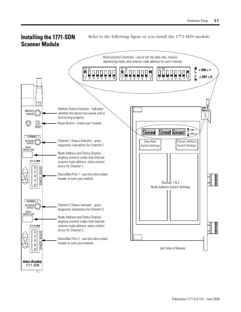
Hardware Setup 3-7Installing the <strong>1771</strong>-SDN<strong>Scanner</strong> ModuleRefer to the following figure as you install the <strong>1771</strong>-SDN module.Multi-position Switches - use to set the data rate, chassisaddressing mode, and scanner node address for each channel.O NO NO N= ON = 11 2 3 4 5 6 7 8 1 2 3 4 5 6 7 8 1 2 3 4 5 6 7 8= OFF = 0MODULESTATUSRESETModule Status Indicator - indicateswhether the device has power and isfunctioning properly.Reset Button - resets your module.= ON = 1CHANNEL 1NETWORKSTATUSNODE/ERROR CODE<strong>DeviceNet</strong>Channel 1 Status Indicator - givesdiagnostic indications for Channel 1.Node Address and Status Display -displays numeric codes that indicatescanner node address, status and/orerrors for Channel 1.Data RateSwitch Settings= OFF = 0Chassis AddressSwitch Settings<strong>DeviceNet</strong> Port 1 - use the color-codedheader to wire your module.Channel 1 & 2Node Address Switch SettingsCHANNEL 2NETWORKSTATUSNODE/ERROR CODE<strong>DeviceNet</strong>Channel 2 Status Indicator - givesdiagnostic indications for Channel 2.Node Address and Status Display -displays numeric codes that indicatescanner node address, status and/orerrors for Channel 2.<strong>DeviceNet</strong> Port 2 - use the color-codedheader to wire your module.Left Side of ModuleAllen-Bradley<strong>1771</strong>-SDNPublication <strong>1771</strong>-<strong>6.5.132</strong> - June 2000