leStrade n. 1956 aprile 2024
INFRASTRUTTURE Milano Serravalle Milano Tangenziali La sicurezza in tempo reale GALLERIE La Realtà Virtuale “avanza” nelle gallerie BBT
INFRASTRUTTURE
Milano Serravalle Milano Tangenziali La sicurezza in tempo reale
GALLERIE
La Realtà Virtuale “avanza” nelle gallerie BBT
- No tags were found...

Create successful ePaper yourself
Turn your PDF publications into a flip-book with our unique Google optimized e-Paper software.
i di spostamento per misurare le rotazioni e gli<br />
spostamenti degli appoggi. Infine, i termometri<br />
sono stati installati in modo da rilevare la temperatura<br />
in tutta l’area di interesse delle strutture.<br />
I sensori sono stati cablati e collegati ad un dispositivo<br />
di sincronizzazione satellitare e ad un’unità<br />
di controllo locale (UCL) che gestisce tutti gli elementi<br />
per la connessione del BUS di trasmissione<br />
in fibra ottica, l’acquisizione dei dati dai sensori<br />
di campo, la loro organizzazione in database e la<br />
preparazione per il loro invio al cloud.<br />
Il viadotto dei Parchi e i sensori a fibra<br />
ottica distribuiti (DOFS)<br />
Il viadotto dei Parchi costituisce l’opera più importante<br />
della Tangenziale est di Milano (A51). Il<br />
progetto originario, firmato dall’ing. Silvano Zorzi,<br />
risale al 1970 e presenta una struttura tipo costituita<br />
da una piastra di impalcato, continua e<br />
solidale con le pile, con luci di 24 metri, con punto<br />
di momento nullo imposto, per ciascuna campata,<br />
a 7 metri dall’asse pila, e materializzato da<br />
una sella tipo Gerber. Le due carreggiate autostradali<br />
sono sostenute da due viadotti aventi le<br />
caratteristiche descritte e tra loro paralleli con interasse<br />
di circa 29 ÷ 30 metri, con uno sviluppo<br />
di circa 3.000 metri.<br />
Nel 1992, in concomitanza con la realizzazione<br />
della terza corsia della Tangenziale Est di Milano,<br />
anche le strutture del viadotto dei parchi sono<br />
state allargate. L’interasse tra i due viadotti ha<br />
reso possibile la realizzazione di due nuove strutture,<br />
una per ciascuna carreggiata, nello spazio<br />
interno tra le due esistenti (fig. 4).<br />
Il notevole sviluppo e il numero di campate dell’opera<br />
ha suggerito l’adozione, per l’acquisizione<br />
delle misure di temperatura, deformazioni e vibrazioni,<br />
di un sistema di sensori distribuiti in fibra<br />
ottica (DOFS).<br />
Questi sensori si distinguono da quelli “discreti”,<br />
spesso utilizzati per le misure su manufatti stradali<br />
e ponti, generalmente basati su reticoli a fibra<br />
di tipo Bragg (FBG) inseriti in fibre ottiche.<br />
Questi dispositivi misurano la deformazione puntuale<br />
tramite una tecnica spettroscopica e sono<br />
di solito usate in catene di qualche decina di punti.<br />
Per tale motivo possono misurare solo qualche<br />
centinaio di punti su distanze relativamente<br />
brevi, sono fragili (perché ottenuti con una lavorazione<br />
della fibra ottica che ne pregiudica l’integrità)<br />
e di difficile posa in opera.<br />
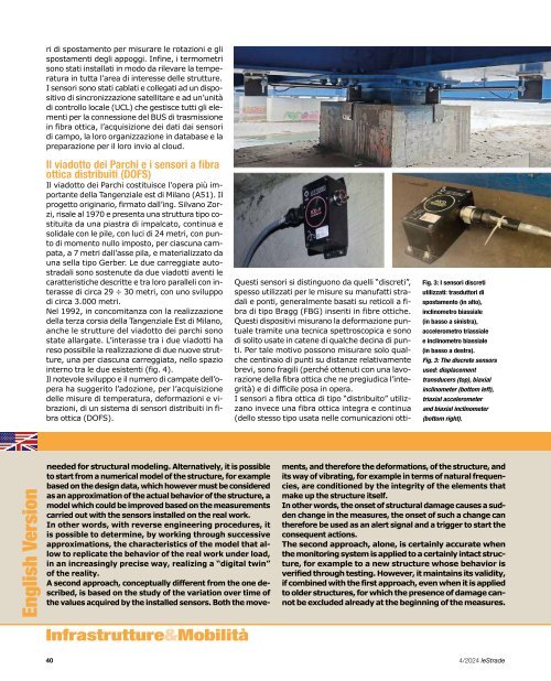
I sensori a fibra ottica di tipo “distribuito” utilizzano<br />
invece una fibra ottica integra e continua<br />
(dello stesso tipo usata nelle comunicazioni otti-<br />
Fig. 3: I sensori discreti<br />
utilizzati: trasduttori di<br />
spostamento (in alto),<br />
inclinometro biassiale<br />
(in basso a sinistra),<br />
accelerometro triassiale<br />
e inclinometro biassiale<br />
(in basso a destra).<br />
Fig. 3: The discrete sensors<br />
used: displacement<br />
transducers (top), biaxial<br />
inclinometer (bottom left),<br />
triaxial accelerometer<br />
and biaxial inclinometer<br />
(bottom right).<br />
Fig. 4: Il viadotto dei Parchi<br />
dopo l’allargo dei primi anni<br />
Novanta.<br />
Fig. 4: The “Viadotto dei<br />
Parchi” after the widening in<br />
the early nineties.<br />
Fig. 5: Disposizione delle<br />
fibre DOFS sulla sezione<br />
trasversale d’una carreggiata.<br />
Fig. 5: Arrangement of DOFS<br />
fibers on the cross section<br />
of a roadway.<br />
che) che viene resa solidale alla struttura da monitorare<br />
con opportuna malta. La fibra ottica trasduce<br />
le informazioni termiche (temperatura) e<br />
meccaniche (allungamenti, deformazioni, vibrazioni)<br />
della struttura e viene letta da interrogatori<br />
dedicati. Le misure distribuite si basano su una<br />
rilevazione del fenomeno di diffusione, o scattering,<br />
che nasce all’interno della fibra al passaggio<br />
della radiazione luminosa. In particolare, il brevetto<br />
[2] utilizzato si basa sull’effetto non-lineare<br />
Brillouin che restituisce una misura assoluta<br />
della deformazione della fibra con risoluzione<br />
di qualche micro-epsilon in deformazione e risoluzione<br />
spaziale che può essere variata da qualche<br />
metro sino a qualche centimetro (in funzione<br />
del tempo di interrogazione). La misura viene<br />
compensata automaticamente in temperatura,<br />
un parametro che è possibile leggere usando lo<br />
stesso interrogatore.<br />
Con la stessa fibra ottica, inoltre, è possibile effettuare<br />
una misura integrale [3] attraverso la<br />
rilevazione interferometrica integrale dell’allungamento<br />
della fibra che restituisce lo stato di allungamento<br />
della struttura nello spettro di frequenza.<br />
Si possono così evidenziare i modi di<br />
vibrazione della struttura [4], le vibrazioni dovute<br />
alle fluttuazioni del carico ed ogni altro evento<br />
dinamico ed impulsivo con altissima sensibilità<br />
(tipica della interferometria ottica), real-time<br />
e senza limiti di frequenza.<br />
I sensori utilizzati per il monitoraggio del viadotto<br />
dei parchi sono un brevetto di proprietà<br />
di una società spin off del Politecnico di Milano e<br />
sono stati installati in direzione longitudinale alla<br />
struttura, sia in corrispondenza dell’intradosso<br />
che dell’estradosso dell’impalcato, nelle posizioni<br />
rappresentate in figura 5, in modo da poter combinare<br />
le deformazioni per ottenere le curvature<br />
e quindi i momenti sollecitanti agenti.<br />
English Version<br />
needed for structural modeling. Alternatively, it is possible<br />
to start from a numerical model of the structure, for example<br />
based on the design data, which however must be considered<br />
as an approximation of the actual behavior of the structure, a<br />
model which could be improved based on the measurements<br />
carried out with the sensors installed on the real work.<br />
In other words, with reverse engineering procedures, it<br />
is possible to determine, by working through successive<br />
approximations, the characteristics of the model that allow<br />
to replicate the behavior of the real work under load,<br />
in an increasingly precise way, realizing a “digital twin”<br />
of the reality.<br />
A second approach, conceptually different from the one described,<br />
is based on the study of the variation over time of<br />
the values acquired by the installed sensors. Both the movements,<br />
and therefore the deformations, of the structure, and<br />
its way of vibrating, for example in terms of natural frequencies,<br />
are conditioned by the integrity of the elements that<br />
make up the structure itself.<br />
In other words, the onset of structural damage causes a sudden<br />
change in the measures, the onset of such a change can<br />
therefore be used as an alert signal and a trigger to start the<br />
consequent actions.<br />
The second approach, alone, is certainly accurate when<br />
the monitoring system is applied to a certainly intact structure,<br />
for example to a new structure whose behavior is<br />
verified through testing. However, it maintains its validity,<br />
if combined with the first approach, even when it is applied<br />
to older structures, for which the presence of damage cannot<br />
be excluded already at the beginning of the measures.<br />
The monitoring system described below, adopted by Milano<br />
Serravalle Milano Tangenziali S.p.A., involving structures<br />
which, in general, have been in operation for over 50<br />
years, was based on the combination of both approaches<br />
mentioned above.<br />
More precisely, through different types of sensors, measurements<br />
are acquired in terms of accelerations of the<br />
decks in the three directions of space and in different<br />
points, in terms of temperatures of the structures, of relative<br />
displacements between piles and decks, and of rotations<br />
in the longitudinal and transversal direction in correspondence<br />
with the piles.<br />
All the measurements, acquired and synchronized for each<br />
individual structure, are transmitted via optical fiber to a<br />
cloud platform which reprocesses them for the calculation,<br />
for example, of the natural vibration frequencies or<br />
displacements. The results are then compared with those<br />
deduced from a very detailed finite element model which,<br />
with reference to certain situations (for example with an<br />
unloaded structure) and through artificial intelligence algorithms,<br />
is iteratively “updated” until it becomes a real<br />
own digital twin.<br />
The digital twin is finally used to calculate the stress values<br />
of the individual components of the work (for example:<br />
concrete, reinforcing bars, pre-compression cables)<br />
and to evaluate their exploitation coefficients compared<br />
to the maximum permitted by law (fig. 2).<br />
Furthermore, the user interface dashboard also synthetically<br />
represents the dynamic behavior of the work in the<br />
frequency field.<br />
Infrastrutture&Mobilità<br />
40 4/<strong>2024</strong> <strong>leStrade</strong><br />
<strong>leStrade</strong> 4/<strong>2024</strong> 41