full Paper - Nguyen Dang Binh
full Paper - Nguyen Dang Binh
full Paper - Nguyen Dang Binh

Create successful ePaper yourself
Turn your PDF publications into a flip-book with our unique Google optimized e-Paper software.
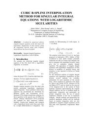
Figure 22: An example of arm trajectory recorded to derive quantitative<br />
requirements for the actuation system<br />
analyse intrinsically 3D solution, such as the transmission<br />
system described in Subsection 7.1. Moreover, it has been<br />
possible an iterative process of design, by changing the dimensional<br />
parameters of a part in consequence of the results<br />
of the analyses performed on the whole system.<br />
Secondly, a software tool has been developed in order to<br />
evaluate the lowest resonant mode associated to the multi<br />
DOFs, coupled transmission system. Such tool implements<br />
the dynamic model of such type of tendon driven robot.<br />
Finally, a dynamical simulation software application has<br />
been developed to evaluate quantitatively the performance<br />
required to the actuators (see Section 8.1.<br />
8.1. Dynamical simulation tool<br />
The derivation of quantitative requirements for the actuators<br />
has been based on the following specifications:<br />
A the kinematics and dynamics of the device, in terms of<br />
joint variables;<br />
B the transmission structure, in terms of the relationship it<br />
introduces between joint variables and motor variables;<br />
C a description of the arm free movements workspace, in<br />
terms of joint positions, velocities, accelerations during<br />
the expected usage of the device. Since the haptic device<br />
has no repetitive usage, a quite large set of typical operation<br />
has been chosen and arm trajectory acquisition has<br />
been done using infrared markers attached on user arm<br />
(see Figure 22 for an example trajectory).<br />
D a specification of the peak forces the haptic device is requested<br />
to apply on the human arm.<br />
c The Eurographics Association 2005.<br />
Massimo Bergamasco / Haptic Interfaces<br />
19<br />
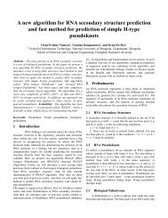
Figure 23: Anthropomorphic haptic device for the upper limb in<br />
reference posture<br />
Given the complexity of the anthropomorphic haptic device,<br />
the first two items have been determined with confidence<br />
only thanks to the adoption of a 3D CAD environment<br />
capable of computing masses and inertia of the complex assemblies<br />
of mechanical parts, which forms the links of the<br />
device.<br />
Items A,B,C and D have been used as inputs to the dynamical<br />
simulation software tool (see the precedent Section)<br />
which solves the inverse dynamic problem along all the arm<br />
trajectories and computes the associated motor trajectories,<br />
under the hypothesis of rigid transmissions. From the motor<br />
trajectories, a set of indexes, such as peak continuous<br />
and rms values of motor torque, velocity, acceleration and<br />
mechanical power output are computed. These values have<br />
been used to select the motors (see Table 3).<br />
9. Design solutions<br />
The device closely follows the human arm from the shoulder<br />
to the palm; it features 7 rotational joints in order to <strong>full</strong>y<br />
preserve the freedom of movement of the user arm (see Figure<br />
23 for an global view).<br />
The choices, already experienced in the Arm Exoskeleton,<br />
of a totally anthropomorphic kinematics and of the usage<br />
of electrical actuation, cable transmission and joint torque<br />
control approach, have been renewed.<br />
The kinematic congruence of the device to the user arm<br />
kinematics is guaranteed by means of a regulation system<br />
for the arm and forearm links. The lengths of the arm link<br />
and the forearm link are continuously adjustable within a<br />
range of 005m and 003m. The adjustments induce no rotation<br />
on the actuators and they can be performed with the<br />
device powered and controlled by a special software.