full Paper - Nguyen Dang Binh
full Paper - Nguyen Dang Binh
full Paper - Nguyen Dang Binh

You also want an ePaper? Increase the reach of your titles
YUMPU automatically turns print PDFs into web optimized ePapers that Google loves.
G. Cini, A. Frisoli, S. Marcheschi, F. Salsedo, M. BergamascoPERCRO Scuola Superiore S. Anna, Italy / Future directions<br />
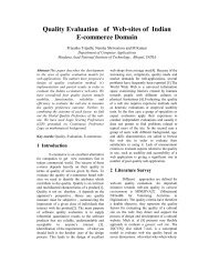
Figure 8: The device is driven by a set of a sheathed tendons<br />
connected to the motorization group<br />
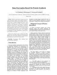
Figure 9: The CAD model of the final design<br />
6. Control of the device<br />
The scheme in Figure 11 represents the actuation system of<br />
one leg, composed of of one motor, the sheathed tendon, the<br />
actuation cable and the return spring for each leg.<br />
The dynamic equations of the motor for each leg were<br />
assumed as follows:<br />
<br />
τm − Tinr = Jm ¨θ + bm ˙θ<br />
(1)<br />
Tout = Kmx + m ¨x = r(Kmθ + m¨θ)<br />
where Jm and bm are respectively the motor inertia and<br />
damping constant, τm is the motor torque, Tin and Tout represent<br />
the cable tension, τm the motor torque, Km the spring<br />
axial stiffness, while x0 is the length at rest of the spring Km.<br />
The friction of the sheath has been modeled according<br />
to the theory of belt (β and f representing respectively the<br />
winding angle of the tendon on the pulley and the friction<br />
coefficient between the groove and the cable) plus a viscous<br />
coefficient b. The relation between Tin and Tout was determined<br />
by the direction of motion, according to the drive ei-<br />
c○ The Eurographics Association 2005.<br />
49<br />
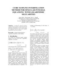
Figure 10: The final implementation of the first prototype<br />
ther by the motor or by the spring.<br />
<br />
Tin = Toute f β + b˙θ = Tout(1 + µ) + b˙θ<br />
Tin =<br />
if ˙θ > 0<br />
Tout<br />
e f β + b˙θ = Tout<br />
(1+µ) + b˙θ if ˙θ < 0<br />
Motor Jm bm<br />
r<br />
Tin<br />
θ<br />
sheath<br />
Tout<br />
Km<br />
Figure 11: Scheme of the actuation system of one leg<br />
The control was implemented with local position controllers<br />
at the joint level. An inverse kinematic module was<br />
used to convert the desired position expressed in cartesian<br />
coordinates to the corresponding joint coordinates. The<br />
non-linear term due to the spring pre-load Kmx0 was precompensated,<br />
by adding it in feedforward to the motor<br />
torque τm in the control loop.<br />
In order to compensate the friction generated by the<br />
sheath, a simple experimental apparatus was set-up to measure<br />
the values of the friction coefficients between the steel<br />
cable and the sheath in different geometric configurations<br />
(for different curvature radii). The cable was fixed on one<br />
side to a position-controlled DC motor and on the other one<br />
to a weight of known mass. The motor was then moved on a<br />
trajectory with constant speed, in order to lift the weight at<br />
constant velocity.<br />
6.1. Experimental results from control<br />
Figure 12 reports the step response of the translational stage<br />
of the system in two opposite directions. The observed dif-<br />
lo<br />
m<br />
X<br />
(2)