full Paper - Nguyen Dang Binh
full Paper - Nguyen Dang Binh
full Paper - Nguyen Dang Binh

Create successful ePaper yourself
Turn your PDF publications into a flip-book with our unique Google optimized e-Paper software.
Table 4: Master and Slave position vectors<br />
Symbol Meaning<br />
P M P S<br />
R M S<br />
O M S<br />
position of spherical joint centre<br />
respect to local frame of master<br />
and slave arm<br />
rotation matrix from master’s<br />
local frame<br />
to slave’s one<br />
position vector of slave’s local<br />
frame respect to master’s one<br />
Since the control procedure will provide to use the right<br />
arm as motion driver, in the following it will be indicated as<br />
master arm and the other one as slave.<br />
As mentioned before, the control procedure will provide<br />
to store the positions of the path points expressed respect to<br />
local frame of two arms (Table 4).<br />
By using any free set of three among the stored points (P M 0<br />
P M 1 P M 2 respect to master’s frame and P S 0 P S 1 P S 2 respect to<br />
slave’s one), it is possible identify a mobile reference frame<br />
which is uniquely identi£ed in both reference systems (Σ0<br />
and Σ1).<br />
Such a system can be used to £nd the rotation matrix between<br />
master’s and slave’s local frames by the following procedure:<br />
1. using stored point it is possible to determine two intermediate<br />
frames with versors<br />
i =(P1 − P0)/|P1 − P0|<br />
Massimo Bergamasco / Haptic Rendering: Control Strategy<br />
j =(P2 − P0) − ((P2 − P0) ·<br />
i)i k =i ×j<br />
2. the rotation matrixes between the master’s local frame<br />
and the intermediate frame and between the slave’s local<br />
frame and the intermediate frame simply result<br />
R M I =[i M ,j M ,k M ] R S I =[i S ,j S ,k S ]<br />
3. the rotation matrix between the master’s local frame and<br />
the slave’s local frame simply results<br />
R M S = R M I (R S I )T<br />
4. Once rotation matrix is known, by using one of three<br />
stored points P0P1P2 (for example P0) it is possible to<br />
£nd the origin position vector of slave’s local frame respect<br />
to master’s one:<br />
O M S = P M 0 −R M S P S 0<br />
It worths to mention that the procedure is independent from<br />
the speci£c trajectory used to £nd the six points set (P M 0<br />
P M 1 P M 2 P S 0 P S 1 P S 2 ). Therefore even in presence of unaccurate<br />
position control the calibration procedure can provide<br />
exact calibration provided that a synchronized and accurate<br />
measure of these points is available.<br />
64<br />
Errors in evaluating stored vectors position can occur<br />
when the procedure is carried on. The reasons could be<br />
within the following ones:<br />
mechanical device could be different from simpli£ed<br />
kinematic model:<br />
– dimensions of mechanical parts may slightly differs respect<br />
to design speci£cations;<br />
– the mechanical device is not absolutely rigid therefore<br />
elasticity of transmissions and of structures may alter<br />
the effective measurement;<br />
– backlash of coupled mechanical parts;<br />
error in angular offsets evaluation, that will led to imprecise<br />
calibration procedure and digital resolution of incremental<br />
position sensors can affect computational procedures.<br />
In order to reduce calibration errors, a recursive procedure<br />
has been implemented by storing a large number of points<br />
and by calculating £nal relative position and orientation between<br />
two frames using average values.<br />
The procedure adopted is the follow:<br />
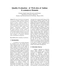
1. master arm is controlled in order to move the centre of<br />
Cardano’s joint along a circumference as shown in Fig.<br />
6;<br />
2. a number of circumference points are stored as indicated<br />
during the movement;<br />
3. a group of three points (P0 P1 P2)i are considered for determining<br />
the correspondent matrix rotation (R M S )i;<br />
4. from any rotation matrix it is necessary to associate the<br />
Roll-Pitch-Yaw angles ( RPY )i;<br />
5. the £nal RPY are calculated as the average values;<br />
6. from the £nal RPY is calculated the £nal rotation matrix.<br />
8. Results<br />
Once the calibration has been achieved the control software<br />
provides to store it in speci£c OS registry entries and reuse<br />
them whenever the system is restarted.<br />
In this way the user can operate on the systems as the<br />
arms belong to unique OS without caring too much (nor in<br />
use, nor in SW development) with the organization of mechanics<br />
and system control. If the user will notice that collocation<br />
of objects within VE appears to be corrupted he can<br />
manage a recalibration of the device at any time. This can<br />
be achieved by issuing the relative command from the HI<br />
control panel. Some extensive tests have been carried out in<br />
order to match the effectiveness of the calibration all over the<br />
workspace. The procedure works as follows: different “virtual”<br />
axes-aligned square-boxes have been placed on several<br />
positions of the arms workspace. HIs have then been moved<br />
onto the boxes in order to arrange thimbles is a parallel fashion<br />
on the same surface. Relative position has been measured<br />
according to the normal to the considered surface. Whenever<br />
c○ The Eurographics Association 2005.