full Paper - Nguyen Dang Binh
full Paper - Nguyen Dang Binh
full Paper - Nguyen Dang Binh

You also want an ePaper? Increase the reach of your titles
YUMPU automatically turns print PDFs into web optimized ePapers that Google loves.
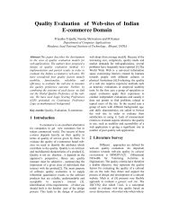
Figure 6: The pinching haptic interface<br />
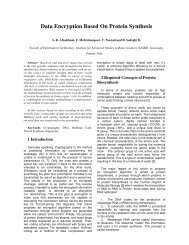
tual objects. Low DOF HIs represent an alternative choice,<br />
when it is not requested to sense the posture of the entire human<br />
arm and the nature of the performed task can be carried<br />
out with a single contact point. An example of such a device<br />
is the desktop two Haptic Interface system realized at PER-<br />
CRO, shown in Figure 7. Such a 2 DOF HI [5] is actuated<br />
by a novel transmission system, which allows increasing the<br />
isotropic behavior of the system force response. The HI can<br />
exert forces up to 10 N in its plane. Although the system<br />
possesses a plane geometry, it can be used for rendering 3dimensional<br />
shapes too, by exploiting vector fields of lateral<br />
forces: a force resistant to the motion of the operator’s hand<br />
and lying in the plane of motion is perceived as a positive<br />
slope, while a force pushing along the motion direction as a<br />
negative slope. This effect has been exploited in numerous<br />
investigations [11] to display virtual features, such as holes<br />
or bumps. The main advantage of a desktop device is the<br />
reduced cost with respect to higher DOF HIs.<br />
Figure 7: The desktop 2 DOF HI<br />
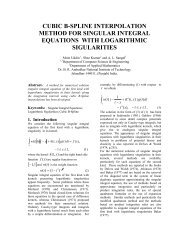
The system is controlled in real-time through a control<br />
system based on two main treads running with different<br />
clocks, according to the architecture shown in Figure 8. Two<br />
different nodes manage the execution of the two threads.<br />
Massimo Bergamasco / Future trends and Applications, Engineering<br />
69<br />
The Haptic Module is executed on a DSpace Control Board,<br />
while the Graphics Module is executed on a Pentium III<br />
1GHz equipped with a NVidia GetForce3 Graphics Board.<br />
Figure 8: Block representation of system architecture<br />
The thread that manages the graphic representation of the<br />
overall virtual environment is executed at each 30 msec and,<br />
detects primitives that are in contact each other in the Virtual<br />
Environments by means of a collision detection algorithm.<br />
In the case of the planar kinematics, it has been adopted<br />
a collision detection algorithm based on the generation of<br />
Voronoi diagrams and distance fields of colliding primitives<br />
using graphics hardware. Such an algorithm, developed for<br />
Computer Graphics purpose only [8], has been integrated<br />
with a hierarchical collision detection algorithm and adapted<br />
in order to fulfill the requirements of force feedback generation.<br />
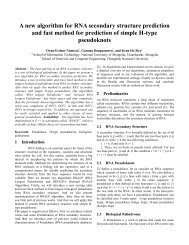
Figure 9 shows the concept underlying the collision detection<br />
algorithm in a simple case of contact between a point<br />
and a circle, represented by means of polygonal representation.<br />
When the point is closed to the circle, Voronoi diagrams<br />
are computed in a square area surrounding the point. Such an<br />
area is divided in sub-areas with different colors, each different<br />
color identifying the polygon edge that is closest to the<br />
point.<br />
Figure 9: Example of Voronoi Diagram associated to the<br />
contact of point with a circle<br />
On the basis of the contact primitives, a local model of<br />
the virtual environment is extracted by selecting neighbors<br />
of the primitives that are in proximity of the contact point.<br />
Such local model is then sent to the Haptic Module, which<br />
generates the force feedback at a refresh rate of 10 KHz.<br />
The Haptic Module is based on a Fast Collision Algorithms<br />
incorporating a God-Object for the computation of forces,<br />
according to [9]. Figures 10,11,12 show a sequence of different<br />
frames of a virtual simulation of insertion of peg in<br />
the hole. When the peg is pushed against a boundary of the<br />
c The Eurographics Association 2005.