full Paper - Nguyen Dang Binh
full Paper - Nguyen Dang Binh
full Paper - Nguyen Dang Binh

You also want an ePaper? Increase the reach of your titles
YUMPU automatically turns print PDFs into web optimized ePapers that Google loves.
force (kg), position (cm)<br />
8<br />
7<br />
6<br />
5<br />
4<br />
3<br />
2<br />
1<br />
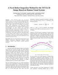
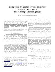
Force and position output of numerical simulation<br />
synchronizing<br />
force<br />
impact force<br />
0<br />
10.6 10.7 10.8 10.9<br />
time (sec)<br />
11 11.1<br />
Massimo Bergamasco / Crating haptic response<br />
engagement<br />
position<br />
force<br />
position<br />
Figure 9: Force and position vs. time output by the numerical<br />
simulation<br />
transmission system, both to increase the motor torques and<br />
to reduce the mechanical plays between motors and potentiometers.<br />
Since our aim was to test the efficiency of the algorithm,<br />
we excluded the built-in control processor, and connected<br />
the Joystick to a high performance control board (DSP<br />
DS1102 dSPACE). By a rough estimation of the maximum<br />
actuated force at the knob with the DSP arrangement, we<br />
found a value of about 10N, that is one tenth of the target<br />
force of 10Kg we wished to replicate. Also the workspace<br />
dimensions were smaller than the required ones. So the presented<br />
results was scaled to the experimental ones of figures<br />
5, just to test the validity of the control algorithm.<br />
We interfaced the Joystick to the Matlab environments<br />
through the Real Time Workshop toolbox. The model was<br />
downloaded and run directly on the DSP board. A GUI interface<br />
panel was developed to control and capture the data<br />
of the simulation.<br />
All simulations were performed at a frequency of 1 KHz<br />
to avoid problems related to simulation sampling time.<br />
First we tested the force feedback during pure engagement<br />
operations. The force-feedback control scheme was based<br />
on a admittance force-display [RB99], which measures force<br />
and displays motion. The forces were estimated by the current<br />
inputs, sent to the motor drives, while the positions were<br />
read by two analogical potentiometers.<br />
During simulation the y position of the joystick was constrained<br />
to zero to simulate a 1 DOF sliding constrain.<br />
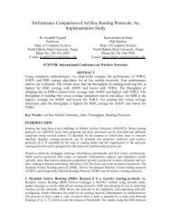
The following plots show the obtained results. The error<br />
on the force signal was determined by the electric noise produced<br />
by the analog potentiometers. Plot 10 shows the filtered<br />
(with a low pass Butterworth filter and a cut-off frequency<br />
of 20 Hz) and the non-filtered signal. The curve<br />
43<br />
matches satisfactorily the experimental one, and also the<br />
feeling during the engagement was realistic and similar to<br />
a slow gear engagement during drive. The hardware restrictions<br />
did not allow to improve further the performance of<br />
the system (position signal resolution and noise, internal mechanical<br />
play, friction), but the devised control law seemed<br />
to work properly.<br />
force (kg), position (cm)<br />
9<br />
8<br />
7<br />
6<br />
5<br />
4<br />
3<br />
2<br />
1<br />
synchronizing<br />
Force vs. time (filtered and unfiltered signal)<br />
FORCE<br />
POSITION<br />
engagement<br />
stop<br />
impact<br />
0<br />
6.2 6.4 6.6 6.8 7<br />
time (sec)<br />
7.2 7.4 7.6 7.8<br />
Figure 10: Force signal estimated from the position error<br />
force (kg)<br />
10<br />
8<br />
6<br />
4<br />
2<br />
0<br />
−2<br />
−4<br />
−6<br />
synchronization<br />
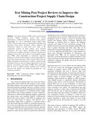
Force−position closed−loop diagram<br />
engagement end<br />
impact<br />
−2 0 2<br />
position (cm)<br />
4 6 8<br />
Figure 11: Force vs. position loop diagram during neutral-<br />
1 st gear shift<br />
After the simulation of a single gear engagement, we<br />
stepped to the development of a complete gearshift. The<br />
model was extended to consider the constrains imposed by<br />
the slides of each gear. The y axis was controlled by using<br />
a parametric module similar to that of the x axis, but with<br />
a lower number of states. In particular the workspace of the<br />
gearshift was divided, according to the x and y, into numerous<br />
areas, associated to a different state of the gearshift. A<br />
main state-flow module, called STATE-FLOW MANAGER,<br />
c The Eurographics Association 2005.