full Paper - Nguyen Dang Binh
full Paper - Nguyen Dang Binh
full Paper - Nguyen Dang Binh

You also want an ePaper? Increase the reach of your titles
YUMPU automatically turns print PDFs into web optimized ePapers that Google loves.
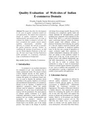
position<br />
OUTPUT2<br />
velocity<br />
OUTPUT1<br />
GEARSHIFT ENGAGEMENT model<br />
GEARSHIFT DYNAMICS<br />
X Position<br />
GS_stage<br />
gs_stage<br />
Massimo Bergamasco / Crating haptic response<br />
x<br />
force<br />
GEARSHIFT STATEFLOW<br />
Driver force<br />
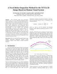
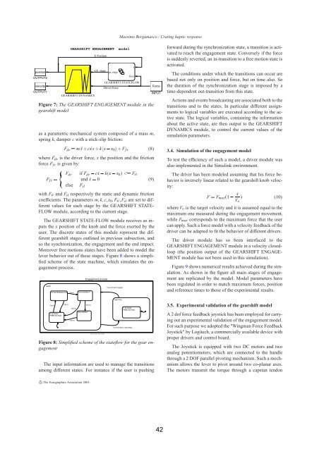
Figure 7: The GEARSHIFT ENGAGEMENT module in the<br />
gearshift model<br />
as a parametric mechanical system composed of a mass m,<br />
spring k, damper c with a stick-slip friction:<br />
Fdr m ¨x c ˙xs k x x0 Ffr (8)<br />
where Fdr is the driver force, x the position and the friction<br />
force Ffr is given by:<br />
Ffr <br />
<br />
<br />
<br />
Fdr if Fdr c ˙x k x x0 Fst<br />
and ˙x 0<br />
else Fsl<br />
with Fst and Fsl respectively the static and dynamic friction<br />
coefficients. The parameters mkcx0FstFsl are set to different<br />
values for each stage by the GEARSHIFT STATE-<br />
FLOW module, according to the current stage.<br />
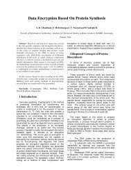
The GEARSHIFT STATE-FLOW module receives as inputs<br />
the x position of the knob and the force exerted by the<br />
user. The discrete states of this module represent the different<br />
gearshift stages outlined in previous subsection, and<br />
so the synchronization, the engagement and the end impact.<br />
Moreover free motions states have been added to model the<br />
lever behavior out of these stages. Figure 8 shows a simplified<br />
scheme of the state machine, which simulates the engagement<br />
process.<br />
GEAR<br />
SYNCHRONIZATION Fdr>0<br />
Fdr>0<br />
X SLIDING<br />
FREE MOTION<br />
ENGAGEMENT<br />
Fdr0<br />
Fdr