full Paper - Nguyen Dang Binh
full Paper - Nguyen Dang Binh
full Paper - Nguyen Dang Binh

Create successful ePaper yourself
Turn your PDF publications into a flip-book with our unique Google optimized e-Paper software.
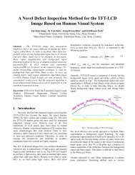
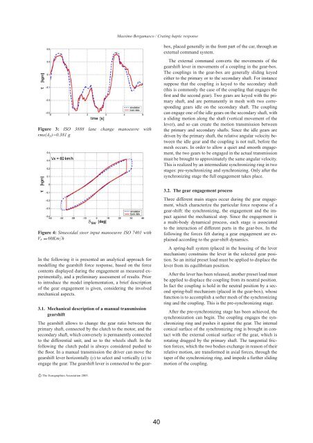
Figure 3: ISO 3888 lane change manoeuvre with<br />
rms(Ay)=0.381 g<br />
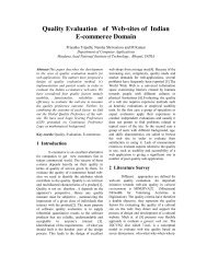
Figure 4: Sinusoidal steer input manoeuvre ISO 7401 with<br />
Vx 60Kmh<br />
In the following it is presented an analytical approach for<br />
modelling the gearshift force response, based on the force<br />
contents displayed during the engagement as measured experimentally,<br />
and a preliminary assessment of results. Prior<br />
to introduce the model implementation, a brief description<br />
of the gear engagement is given, considering the involved<br />
mechanical aspects.<br />
3.1. Mechanical description of a manual transmission<br />
gearshift<br />
The gearshift allows to change the gear ratio between the<br />
primary shaft, connected by the clutch to the motor, and the<br />
secondary shaft, which conversely is permanently connected<br />
to the differential unit, and so to the wheels shaft. In the<br />
following the clutch pedal is always considered pushed to<br />
the floor. In a manual transmission the driver can move the<br />
gearshift lever horizontally (y) to select and vertically (x) to<br />
engage the gear. The gearshift lever is connected to the gear-<br />
c The Eurographics Association 2005.<br />
Massimo Bergamasco / Crating haptic response<br />
40<br />
box, placed generally in the front part of the car, through an<br />
external command system.<br />
The external command converts the movements of the<br />
gearshift lever in movements of a coupling in the gear-box.<br />
The couplings in the gear-box are generally sliding keyed<br />
either to the primary or to the secondary shaft. For instance<br />
suppose that the coupling is keyed to the secondary shaft<br />
(this is commonly the case of the coupling that engages the<br />
first and the second gear). Two gears are keyed with the primary<br />
shaft, and are permanently in mesh with two corresponding<br />
gears idle on the secondary shaft. The coupling<br />
can engage one of the idle gears on the secondary shaft, with<br />
a sliding motion along the shaft (vertical movement of the<br />
lever), and so can create the motion transmission between<br />
the primary and secondary shafts. Since the idle gears are<br />
driven by the primary shaft, the relative angular velocity between<br />
the idle gear and the coupling is not null, before the<br />
mesh occurs. In order to allow a quiet and smooth engagement,<br />
the two gears to be engaged in the actual transmission<br />
must be brought to approximately the same angular velocity.<br />
This is realized by an intermediate synchronizing ring in two<br />
stages: pre-synchronizing and synchronizing. Only after the<br />
synchronizing stage the <strong>full</strong> engagement takes place.<br />
3.2. The gear engagement process<br />
Three different main stages occur during the gear engagement,<br />
which characterize the particular force response of a<br />
gear-shift: the synchronizing, the engagement and the impact<br />
against the mechanical stop. Since the engagement is<br />
a multi-body dynamical process, each stage is associated<br />
to the interaction of different parts in the gear-box. In the<br />
following the forces felt during a gear engagement are explained<br />
according to the gear-shift dynamics.<br />
A spring-ball system (placed in the housing of the lever<br />
mechanism) constrains the lever in the selected gear position.<br />
So an initial preset load must be applied to displace the<br />
lever from its equilibrium position.<br />
After the lever has been released, another preset load must<br />
be applied to displace the coupling from its neutral position.<br />
In fact the coupling is hold in the neutral position by a second<br />
spring-ball mechanism (placed in the gear-box), whose<br />
function is to accomplish a softer mesh of the synchronizing<br />
ring and the coupling. This is the pre-synchronizing stage.<br />
After the pre-synchronizing stage has been achieved, the<br />
synchronization can begin. The coupling engages the synchronizing<br />
ring and pushes it against the gear. The internal<br />
conical surface of the synchronizing ring is brought in contact<br />
with the external conical surface of the gear, which is<br />
rotating dragged by the primary shaft. The tangential friction<br />
forces, which the two bodies exchange in reason of their<br />
relative motion, are transformed in axial forces, through the<br />
taper of the synchronizing ring, and impede a further sliding<br />
motion of the coupling.