Engineering plastics â The Manual - F.wood-supply.dk
Engineering plastics â The Manual - F.wood-supply.dk
Engineering plastics â The Manual - F.wood-supply.dk

Create successful ePaper yourself
Turn your PDF publications into a flip-book with our unique Google optimized e-Paper software.
Calculations<br />
In order to clarify the correlations described under the heading<br />
"Mechanical properties", the described influencing factors<br />
will first be explained in detail using a simple example:<br />
Description:<br />
Let us assume that we have to produce a simple square machine<br />
underlay.<br />
<strong>The</strong> underlay is placed flush with its surface on a level floor<br />
and is exposed over its whole surface to an even load of 1 ton.<br />
Given:<br />
h = 10 mm<br />
w = 50 mm<br />
l = 50 mm<br />
m = 1,000 kg h<br />
w<br />
F G<br />
l<br />
ˌˌCrack formation (application of load until irreversible<br />
damage in the micro-range, crazing)<br />
ˌˌApplication-specific max. admissible deformation<br />
For the application described here, a maximum admissible<br />
deformation of 1 % is assumed.<br />
With this value, the admissible surface compression may<br />
be determined with the aid of a quasi-statistical stressstrain<br />
curve. Even if the stress involved in the described<br />
case is compression stress, it is possible to revert here to<br />
results from the tensile test, as with only a few exceptions<br />
the tensile strength of a material is smaller than the compressive<br />
strength. Consequently, at the same time a certain<br />
safety allowance is also taken into consideration. As the results<br />
of the tensile test are easily accessible, this also means<br />
that a good data base is available.<br />
1. <strong>The</strong> following applies:<br />
To be able to calculate the occurring surface compression,<br />
first of all the weight force is calculated as follows:<br />
F G = m × g = 1,000 kg × 10 m/s² = 10,000 N (simplified)<br />
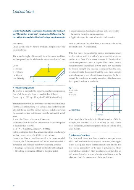
Fig. 1<br />
Stress-strain<br />
curve<br />
PA 66 (dry)<br />
120<br />
100<br />
80<br />
60<br />
120<br />
100<br />
80<br />
60<br />
This force must then be projected onto the contact surface.<br />
For the sake of simplicity, it is assumed that the force is ideally<br />
distributed over the contact surface. Initially, however,<br />
the contact surface in this case must be calculated as follows:<br />
A = w × l = 50 mm × 50 mm = 2,500 mm²<br />
in order to allow the surface compression to be subsequently<br />
calculated as follows:<br />
p = F / A = 10,000N / 2,500 mm² = 4.0 MPa<br />
In the application described above (simplified calculation) a<br />
surface compression of 4.0 MPa is determined.<br />
In order to allow a suitable material to be recommended,<br />
however, the failure criterion still has to be determined. A<br />
distinction can be made here between several criteria:<br />
ˌˌBreakage (application of load until material breakage)<br />
ˌˌStretching (application of load to the yield point)<br />
TECAMID 66<br />
• Stress [MPa]<br />
40<br />
35<br />
20<br />
0<br />
0 1 2 3 4<br />
• Strain [%]<br />
With a load of 4 MPa and admissible deformation of 1%, for<br />
example, the material TECAMID 66 may be used. Under<br />
these conditions, surface compression can be applied up to<br />
appr. 35 MPa<br />
2. Influence of moisture<br />
<strong>The</strong> data used above was determined on test specimens<br />
which had just been freshly injected. However, their application<br />
takes place under normal climatic conditions. For<br />
this reason, particularly in the case of polyamides, which<br />
generally have relatively high moisture absorption, the actual<br />
strength under normal climatic conditions must be<br />
taken as a basis for assessment of the application:<br />
40<br />
20<br />
17<br />
0<br />
72