CLM HD8 - Projector Central
CLM HD8 - Projector Central
CLM HD8 - Projector Central

You also want an ePaper? Increase the reach of your titles
YUMPU automatically turns print PDFs into web optimized ePapers that Google loves.
9. Image menu<br />
9.3.9 Input balance<br />
Overview<br />
• Introduction to Input Balance<br />
• Adjusting the input balance<br />
9.3.9.1 Introduction to Input Balance<br />
Introduction: Unbalanced color signals<br />
When transporting signals, there is always a risk of deterioration of the information contained in the signals.<br />
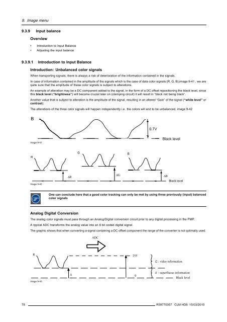
In case of information contained in the amplitude of the signals which is the case of data color signals (R, G, B),image 9-41 , we are<br />
quite sure that the amplitude of these color signals is subject to alterations.<br />
An example of alteration may be a DC component added to the signal, in the form of a DC offset repositioning the black level, since<br />
this black level (“brightness”) will become crucial later on (clamping circuit) it will result in “black not being black”.<br />
Another value that is subject to alteration is the amplitude of the signal, resulting in an altered “Gain” of the signal (“white level” or<br />
contrast).<br />
The alterations of the three color signals will happen independently i.e. the colors will end to be unbalanced, image 9-42<br />
B<br />
0.7V<br />
Image 9-41<br />
Black level<br />
R<br />
G<br />
B<br />
Image 9-42<br />
ΔR<br />
ΔG<br />
ΔΒ<br />
Black level<br />
One can conclude here that a good color tracking can only be met by using three previously (input) balanced<br />
color signals<br />
Analog Digital Conversion<br />
The analog color signals must pass through an Analog/Digital conversion circuit prior to any digital processing in the PMP.<br />
A typical ADC transforms the analog value into an 8 bit coded digital signal.<br />
The graphic shows that when converting a signal containing a DC offset component the range of the converter is not optimally used.<br />
ADC<br />
R<br />
255<br />
i2 : video information<br />
Image 9-43<br />
Δ<br />
0<br />
i1 : superfluous information<br />
Black level<br />
78 R59770057 <strong>CLM</strong> <strong>HD8</strong> 15/03/2010