

CLIOwin 7 PCI User's Manual - Audiomatica
CLIOwin 7 PCI User's Manual - Audiomatica
CLIOwin 7 PCI User's Manual - Audiomatica

You also want an ePaper? Increase the reach of your titles
YUMPU automatically turns print PDFs into web optimized ePapers that Google loves.
150.0<br />
CLIO<br />
180.0<br />
150.0<br />
CLIO<br />
180.0<br />
Ohm<br />
Deg<br />
Ohm<br />
Deg<br />
120.0 108.0<br />
120.0 108.0<br />
90.0 36.0<br />
90.0 36.0<br />
60.0 -36.0<br />
60.0 -36.0<br />
30.0 -108.0<br />
30.0 -108.0<br />
0.0 -180.0<br />
20 Hz<br />
100 1k 10k 20k<br />
0.0 -180.0<br />
3 Hz<br />
10 100 1k<br />
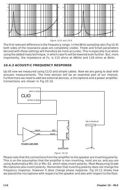
Figure 10.8 and 10.9<br />
The first relevant difference is the frequency range. In the 8kHz sampling rate (Fig 10.9)<br />
both sides of the resonance peak are completely visible. Thiele and Small parameters<br />
derived with these settings will therefore be more accurate. This is especially true when<br />
using the added mass technique, in which case Fs will be lowered even further. But, more<br />
importantly, the impedance at Fs, is 115 ohms at 48kHz and 118 ohms at 8kHz.<br />
10.4.3 ACOUSTIC FREQUENCY RESPONSE<br />
Up till now we measured using CLIO and simple cables. Now we are going to deal with<br />
acoustic measurements. The time domain will be an essential part of our interest.<br />
Furthermore we need to add two external devices, a microphone and a power amplifier.<br />
Connections are shown in Fig.10.10.<br />
CLIO<br />
INPUT (A OR B)<br />
OUTPUT (A OR B)<br />
MIC-01 OR MIC-02<br />
BLACK<br />
RED<br />
RED<br />
BLACK<br />
POWER AMPLIFIER<br />
Figure 10.10<br />
Please note that the connections from the amplifier to the speaker are inverting polarity.<br />
This is on the assumption that the amplifier is non-inverting, most are so, and you are<br />
using <strong>Audiomatica</strong> Mic-01 or Mic-02, which does invert polarity. Most Measuring Grade<br />
Microphones also invert polarity. Remember that inverting polarity does not change the<br />
frequency response, however it does change phase response. Fig.10.11 shows how<br />
we placed the microphone with respect to the speaker and also with respect to the floor.<br />
116 Chapter 10 - MLS


