

Tutorials Manual
Tutorials Manual
Tutorials Manual

Create successful ePaper yourself
Turn your PDF publications into a flip-book with our unique Google optimized e-Paper software.
Chapter 2: Combustion in Gas-phase Processes<br />
<strong>Tutorials</strong> <strong>Manual</strong><br />
2.6.1.3 Project Results<br />
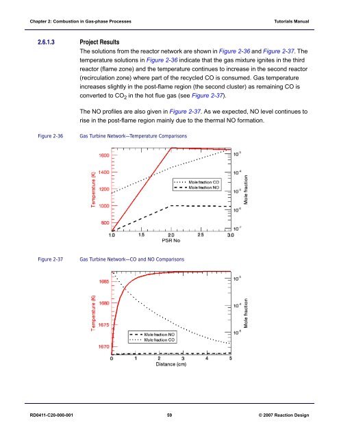
The solutions from the reactor network are shown in Figure 2-36 and Figure 2-37. The<br />
temperature solutions in Figure 2-36 indicate that the gas mixture ignites in the third<br />
reactor (flame zone) and the temperature continues to increase in the second reactor<br />
(recirculation zone) where part of the recycled CO is consumed. Gas temperature<br />
increases slightly in the post-flame region (the second cluster) as remaining CO is<br />
converted to CO 2 in the hot flue gas (see Figure 2-37).<br />
The NO profiles are also given in Figure 2-37. As we expected, NO level continues to<br />
rise in the post-flame region mainly due to the thermal NO formation.<br />
Figure 2-36<br />
Gas Turbine Network—Temperature Comparisons<br />
Figure 2-37<br />
Gas Turbine Network—CO and NO Comparisons<br />
RD0411-C20-000-001 59 © 2007 Reaction Design


