- Page 1 and 2:
AutoVu Handbook 5.1 SR2 Click here
- Page 3 and 4:
Product documentation Security Cent
- Page 5 and 6:
Contents Product documentation . .
- Page 7 and 8:
| Link a camera to an LPR unit . .
- Page 9 and 10:
| Fixed installation procedure . .
- Page 11 and 12:
| Chapter 10: Upgrading AutoVu Upgr
- Page 13 and 14:
| LPR Unit entity . . . . . . . . .
- Page 15 and 16:
| Hotlists . . . . . . . . . . . .
- Page 17 and 18:
About this guide This guide provide
- Page 19 and 20:
1 Introducing AutoVu This section d
- Page 21 and 22:
What is AutoVu? The following diagr
- Page 23 and 24:
AutoVu hardware components • Auto
- Page 25 and 26:
AutoVu software components What is
- Page 27 and 28:
2 AutoVu software interface tours T
- Page 29 and 30:
Security Center Config Tool interfa
- Page 31 and 32:
Patroller Config Tool interface tou
- Page 33 and 34: Patroller Config Tool interface tou
- Page 35 and 36: Sharp Admin interface tour Log off
- Page 37 and 38: Sharp Admin interface tour Benefits
- Page 39 and 40: Where to find the most common tasks
- Page 41 and 42: About the fixed deployment process
- Page 43 and 44: Phase 2: AutoVu software installati
- Page 45 and 46: Phase 4: Configure LPR Manager for
- Page 47 and 48: Phase 4: Configure LPR Manager for
- Page 49 and 50: Phase 4: Configure LPR Manager for
- Page 51 and 52: Phase 4: Configure LPR Manager for
- Page 53 and 54: Phase 5: Configure LPR unit 7 (Opti
- Page 55 and 56: Phase 6: Configure hotlists Phase 6
- Page 57 and 58: Phase 6: Configure hotlists 2 Send
- Page 59 and 60: About the mobile deployment process
- Page 61 and 62: Phase 2: AutoVu software installati
- Page 63 and 64: Phase 4: Configure LPR Manager for
- Page 65 and 66: Phase 4: Configure LPR Manager for
- Page 67 and 68: Phase 4: Configure LPR Manager for
- Page 69 and 70: Phase 5: Configure hotlists Phase 5
- Page 71 and 72: Phase 5: Configure hotlists 1 Send
- Page 73 and 74: Phase 5: Configure hotlists 1 Log o
- Page 75 and 76: Phase 6: Configure Patroller unit s
- Page 77 and 78: Phase 7: Configure Patroller Config
- Page 79 and 80: Phase 7: Configure Patroller NOTE I
- Page 81 and 82: Hardware specifications and system
- Page 83: Safety precautions • Make sure ca
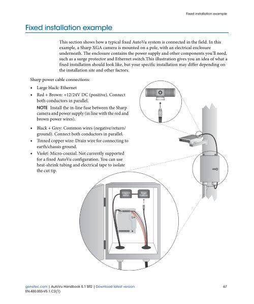
- Page 87 and 88: Fixed installation guidelines Fixed
- Page 89 and 90: Fixed installation guidelines Sharp
- Page 91 and 92: Fixed installation procedure Fixed
- Page 93 and 94: Fixed installation procedure Step 4
- Page 95 and 96: 7 Installing mobile AutoVu hardware
- Page 97 and 98: Mobile installation examples for Sh
- Page 99 and 100: Mobile installation examples for Sh
- Page 101 and 102: Mobile installation examples for Sh
- Page 103 and 104: Mobile installation procedure for S
- Page 105 and 106: Mobile installation procedure for S
- Page 107 and 108: Mobile installation procedure for S
- Page 109 and 110: Mobile installation procedure for S
- Page 111 and 112: Mobile installation procedure for S
- Page 113 and 114: Mobile installation procedure Mobil
- Page 115 and 116: Mobile installation procedure NOTE
- Page 117 and 118: Mobile installation procedure 2 Str
- Page 119 and 120: Mobile installation procedure 2 Cri
- Page 121 and 122: Mobile installation procedure Retur
- Page 123 and 124: 9 Installing Patroller This section
- Page 125 and 126: System requirements Item Wireless c
- Page 127 and 128: Before you install Before you insta
- Page 129 and 130: Installation overview Installation
- Page 131 and 132: Installing AutoVu Patroller NOTE Mi
- Page 133 and 134: Upgrading Patroller and Sharp units
- Page 135 and 136:
Upgrading Patroller and Sharp units
- Page 137 and 138:
Upgrading Patroller and Sharp units
- Page 139 and 140:
Upgrading Patroller Upgrade overvie
- Page 141 and 142:
Upgrade FAQ for Patroller users Upg
- Page 143 and 144:
About advanced configuration About
- Page 145 and 146:
Configure the Sharp for an FTP conn
- Page 147 and 148:
Using a SharpX - Multi system Using
- Page 149 and 150:
Configuring Sharp Admin security Co
- Page 151 and 152:
Configuring Sharp Admin security 7
- Page 153 and 154:
Configuring Sharp Admin security Co
- Page 155 and 156:
Connecting Sharp units to Patroller
- Page 157 and 158:
Connecting Sharp units to Patroller
- Page 159 and 160:
Setting up USB support Set Root fol
- Page 161 and 162:
Setting up USB support 4 Open USB_T
- Page 163 and 164:
Using a SharpX system with multiple
- Page 165 and 166:
Install the GPS driver 8 Click Fini
- Page 167 and 168:
Enabling privacy on individual hotl
- Page 169 and 170:
Moving Patroller or LPR units betwe
- Page 171 and 172:
12 Config Tool reference This secti
- Page 173 and 174:
Common configuration tabs Standard
- Page 175 and 176:
Common configuration tabs Custom fi
- Page 177 and 178:
Common configuration tabs map in Se
- Page 179 and 180:
Hotlist entity Properties The Prope
- Page 181 and 182:
Hotlist entity • Fixed length. Th
- Page 183 and 184:
Hotlist entity • Limit the number
- Page 185 and 186:
LPR Unit entity LPR Unit entity An
- Page 187 and 188:
Patroller entity Patroller entity A
- Page 189 and 190:
Patroller entity • Machine name.
- Page 191 and 192:
User entity Properties The Properti
- Page 193 and 194:
User entity User level Security Cen
- Page 195 and 196:
User entity Workspace The Workspace
- Page 197 and 198:
User group entity User group entity
- Page 199 and 200:
User group entity Security The Secu
- Page 201 and 202:
LPR Manager role LPR Manager role T
- Page 203 and 204:
LPR Manager role the username and p
- Page 205 and 206:
LPR Manager role • Root folder. T
- Page 207 and 208:
LPR Manager role • Accept Non Enc
- Page 209 and 210:
LPR Manager role • Email componen
- Page 211 and 212:
LPR Manager role XML export The XML
- Page 213 and 214:
LPR Manager role XML import The XML
- Page 215 and 216:
LPR administration task LPR adminis
- Page 217 and 218:
LPR administration task • "Update
- Page 219 and 220:
LPR administration task Hotlist The
- Page 221 and 222:
LPR administration task NOTE Before
- Page 223 and 224:
General General The General setting
- Page 225 and 226:
Security Center Security Center Liv
- Page 227 and 228:
Security Center Offload Offloading
- Page 229 and 230:
Plugin Plugin The Plugin page is wh
- Page 231 and 232:
Hits Hits The Hits page allows you
- Page 233 and 234:
Hits Setting Use shared permit Bypa
- Page 235 and 236:
Navigation Navigation The Navigatio
- Page 237 and 238:
Navigation Setting Read when moving
- Page 239 and 240:
User interface Setting Start applic
- Page 241 and 242:
Advanced Mobile patroller hit Setti
- Page 243 and 244:
Status Status The Status page displ
- Page 245 and 246:
Status Actions Displays several act
- Page 247 and 248:
Configuration Configuration The Con
- Page 249 and 250:
Configuration Setting Show settings
- Page 251 and 252:
Configuration • Interface 3 and I
- Page 253 and 254:
Configuration Setting Description P
- Page 255 and 256:
Live feed Live feed The Live feeds
- Page 257 and 258:
Diagnostics Diagnostics Search fiel
- Page 259 and 260:
A SharpX LED status reference This
- Page 261 and 262:
LED status on the LPR Processing Un
- Page 263 and 264:
LED status on the SharpX camera uni
- Page 265 and 266:
AutoVu Sharp parts AutoVu Sharp par
- Page 267 and 268:
AutoVu Sharp parts Understanding th
- Page 269 and 270:
AutoVu SharpX parts a. For more inf
- Page 271 and 272:
Access troubleshooter Access troubl
- Page 273 and 274:
Area activities Area activities Are
- Page 275 and 276:
camera camera Camera events camera
- Page 277 and 278:
Credential activities Credential ac
- Page 279 and 280:
door side door side Door troublesho
- Page 281 and 282:
free access free access free exit G
- Page 283 and 284:
Health history Health history Healt
- Page 285 and 286:
interface module interface module i
- Page 287 and 288:
license plate inventory license pla
- Page 289 and 290:
map link map link Map mode map obje
- Page 291 and 292:
Move unit Move unit MPEG-4 multicas
- Page 293 and 294:
partition partition partition manag
- Page 295 and 296:
PlateReaderServer PlateReaderServer
- Page 297 and 298:
ecording state recording state redi
- Page 299 and 300:
selector selector server Server Adm
- Page 301 and 302:
strict antipassback strict antipass
- Page 303 and 304:
Transmission Control Protocol Trans
- Page 305 and 306:
vehicle identification number vehic
- Page 307 and 308:
Wiegand Wiegand An electrical inter
- Page 309 and 310:
Index | G configuring basic propert
- Page 311 and 312:
Index | R configuring sound managem