OPERATOR'S MANUAL - The Baker Company Blog
OPERATOR'S MANUAL - The Baker Company Blog
OPERATOR'S MANUAL - The Baker Company Blog

Create successful ePaper yourself
Turn your PDF publications into a flip-book with our unique Google optimized e-Paper software.
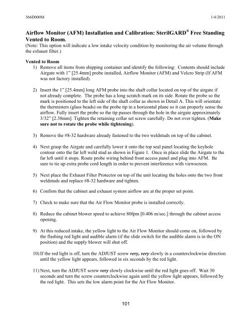
366D000M 1/4/2011Airflow Monitor (AFM) Installation and Calibration: SterilGARD ® Free StandingVented to Room.(Note: This option will indicate a low intake velocity condition by monitoring the air volume throughthe exhaust filter.)Vented to Room1) Remove all items from shipping container and identify the following: Contents should includeAirgate with 1” [25.4mm] probe installed, Airflow Monitor (AFM) and Velcro Strip (If AFMwas not factory installed).2) Insert the 1” [25.4mm] long AFM probe into the shaft collar located on top of the airgate ifnot already complete. <strong>The</strong> probe has a long scratch mark on its side. Rotate the probe so themark is positioned to the left side of the shaft collar as shown in Detail A. This will orientatethe thermisters (glass beads) on the probe tip in a horizontal plane so it can properly sense theairflow. Fully insert the probe so the tip passes through the hole in the airgate approximately3/32” [2.38mm]. Tighten the retaining collar set screw carefully. Do not over tighten. (Makesure not to rotate the probe while tightening).3) Remove the #8-32 hardware already fastened to the two weldstuds on top of the cabinet.4) Next grasp the Airgate and carefully lower it onto the top seal panel locating the keyholecontour onto the far left weld stud as shown in Figure 1. Once in place slide the Airgate to thefar left until it stops. Route probe wiring behind front access panel and plug into AFM. Besure to tie up extra probe cord length in order to prevent interference with viewscreen.5) Next place the Exhaust Filter Protector on top of the unit locating the holes onto the two frontweldstuds and replace #8-32 hardware and tighten.6) Confirm that the cabinet and exhaust system airflow are at the proper set point.7) Check to make sure that the Air Flow Monitor probe is installed correctly.8) Reduce the cabinet blower speed to achieve 80fpm [0.406 m/sec.] through the cabinet accessopening.9) At this reduced intake, the yellow light to the Air Flow Monitor should come on, followed bythe flashing red light and audible alarm (if the slide switch for the audible alarm is in the ONposition) and the supply blower will shut off.10) If the red light is off, turn the ADJUST screw very, very slowly in a counterclockwise directionuntil the yellow light appears, followed in six seconds by the red light.11) Next, turn the ADJUST screw very slowly clockwise until the red light goes off. Wait 30seconds and turn the screw counterclockwise again until the yellow light appears, followed bythe red light. This sets the low alarm point for the Air Flow Monitor.101