OPERATOR'S MANUAL - The Baker Company Blog
OPERATOR'S MANUAL - The Baker Company Blog
OPERATOR'S MANUAL - The Baker Company Blog
You also want an ePaper? Increase the reach of your titles
YUMPU automatically turns print PDFs into web optimized ePapers that Google loves.
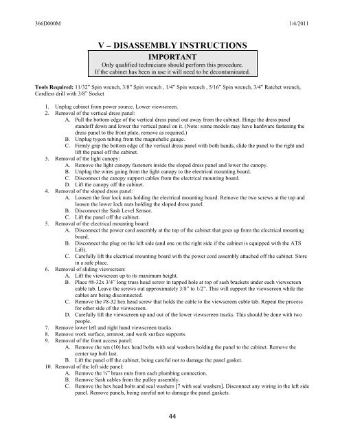
366D000M 1/4/2011V – DISASSEMBLY INSTRUCTIONSIMPORTANTOnly qualified technicians should perform this procedure.If the cabinet has been in use it will need to be decontaminated.Tools Required: 11/32” Spin wrench, 3/8” Spin wrench , 1/4” Spin wrench , 5/16” Spin wrench, 3/4” Ratchet wrench,Cordless drill with 3/8” Socket1. Unplug cabinet from power source. Lower viewscreen.2. Removal of the vertical dress panel:A. Pull the bottom edge of the vertical dress panel out away from the cabinet. Hinge the dress panelstandoff down and lower the vertical panel on it. (Note: some models may have hardware fastening thedress panel to the front plate, remove as required.)B. Unplug tygon tubing from the magnehelic gauge.C. Firmly grip the bottom edge of the vertical dress panel with both hands, slide the panel to the right andlift the panel off the cabinet.3. Removal of the light canopy:A. Remove the light canopy fasteners inside the sloped dress panel and lower the canopy.B. Unplug the wires going from the light canopy to the electrical mounting board.C. Disconnect the canopy support cables from the electrical mounting board.D. Lift the canopy off the cabinet.4. Removal of the sloped dress panel:A. Loosen the four lock nuts holding the electrical mounting board. Remove the two screws at the top andloosen the lower lock nuts holding the sloped dress panel.B. Disconnect the Sash Level Sensor.C. Lift the panel off the cabinet.5. Removal of the electrical mounting board:A. Disconnect the power cord assembly at the top of the cabinet that goes up from the electrical mountingboard.B. Disconnect the plug on the left side (and one on the right side if the cabinet is equipped with the ATSLift).C. Carefully lift the electrical mounting board with the power cord assembly attached off the cabinet. Storein a safe place.6. Removal of sliding viewscreen:A. Lift the viewscreen up to its maximum height.B. Place #8-32x 3/4” long truss head screw in tapped hole at top of sash brackets under each viewscreencable tab. Leave the screws out approximately 3/8” to 1/2”. This will support the viewscreen while thecables are being disconnected.C. Remove the #8-32 hex head screw that holds the cable to the viewscreen cable tab. Repeat the processfor other side of the viewscreen.D. Carefully lift the viewscreen up and out of the lower viewscreen tracks. This should be done with twopeople.7. Remove lower left and right hand viewscreen tracks.8. Remove work surface, armrest, and work surface supports.9. Removal of the front access panel:A. Remove the ten (10) hex head bolts with seal washers holding the panel to the cabinet. Remove thecenter top bolt last.B. Lift the panel off the cabinet, being careful not to damage the panel gasket.10. Removal of the left side panel:A. Remove the ¾” brass nuts from each plumbing connection.B. Remove Sash cables from the pulley assembly.C. Remove the hex head bolts and seal washers [7 with seal washers]. Disconnect any wiring in the left sidepanel. Remove panels, being careful not to damage the panel gaskets.44


