- Page 1 and 2: Hydraulic ram pumps and Sling Pumps
- Page 3 and 4: Hydraulic ram pumps and Sling Pumps
- Page 5 and 6: Use a hydraulic ram pump to continu
- Page 7 and 8: Use a hydraulic ram pump to continu
- Page 9 and 10: Designing a Hydraulic Ram PumpL = T
- Page 11 and 12: Designing a Hydraulic Ram PumpTable
- Page 13 and 14: CAT Publications at www.ecobooks.co
- Page 16 and 17: Atlas Publications-inexpensive how-
- Page 18 and 19: The Development Technology UnitAnim
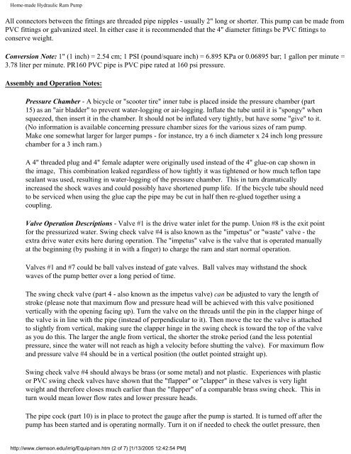
- Page 22 and 23: Home-made Hydraulic Ram Pumpturn it
- Page 24 and 25: Home-made Hydraulic Ram Pumpthe wat
- Page 26 and 27: Home-made Hydraulic Ram Pumphydraul
- Page 28 and 29: Hydraulic Ram Pump6. The length of
- Page 30 and 31: Hydraulic Ram PumpHydram Size 1 2 3
- Page 32 and 33: Hydraulic Ram PumpTable 3 can now b
- Page 34 and 35: Real Goods Catalog - Library & Offi
- Page 36 and 37: Hydraulic Ram Pumps EBAE 161-92Prin
- Page 38 and 39: Hydraulic Ram Pumps EBAE 161-92upon
- Page 40 and 41: Hydraulic Ram Pumps EBAE 161-92Hydr
- Page 42 and 43: Hydraulic Ram Pumps EBAE 161-923. D
- Page 44 and 45: Hydraulic Ram Pump System Design an
- Page 46 and 47: Hydraulic Ram Pump System Design an
- Page 48 and 49: Hydraulic Ram Pump System Design an
- Page 50 and 51: Hydraulic Ram Pump System Design an
- Page 52 and 53: Hydraulic Ram Pump System Design an
- Page 54 and 55: Hydraulic Ram Pump System Design an
- Page 56 and 57: Picture GallerySearch the web with
- Page 58 and 59: Ram Pump (from Internet Glossary of
- Page 60 and 61: Ram Pump (from Internet Glossary of
- Page 62 and 63: Ram Pump (from Internet Glossary of
- Page 64 and 65: Motorless Water Pump--Gravi-Chekhtt
- Page 66 and 67: AEE Renewable Energy SupersourcePut
- Page 68 and 69: Aquatic Eco-Systems - Aquaculture S
- Page 70 and 71:
Real Goods - Folk Ram Pumps
- Page 72 and 73:
Sling Pump (from Internet Glossary
- Page 74 and 75:
Sling Pump (from Internet Glossary
- Page 76 and 77:
Table of ContentsIntroduction _____
- Page 78 and 79:
and limited access configurations.F
- Page 80 and 81:
Ram PumpsRam pumps are very simpleh
- Page 82 and 83:
Nose Pumpsentire pump body.The pump
- Page 84 and 85:
Table 2 - Installation Consideratio
- Page 86 and 87:
Livestock WateringUSING STREAM-POWE
- Page 88 and 89:
Figure 5 Sling PumpInstallation Opt
- Page 90 and 91:
Real Goods - Pump water from stream
- Page 92 and 93:
SlingpumpsRife Hydraulic Engine Mfg
- Page 94 and 95:
Lifewater Canada: Sponsor a WellIf
- Page 96 and 97:
Lifewater Canada: Who We AreAccordi
- Page 98 and 99:
Handpump & Drilling Resources: Pitc
- Page 100 and 101:
Handpump & Drilling Resources: Pitc
- Page 102 and 103:
Handpump & Drilling Resources: Pitc
- Page 104 and 105:
Handpump & Drilling Resources: Pitc
- Page 106 and 107:
Lifewater Canada: The SolutionLifew
- Page 108 and 109:
Lifewater Canada: The SolutionProje
- Page 110 and 111:
safe water - the gift of life - giv
- Page 112 and 113:
safe water - the gift of life - giv
- Page 114 and 115:
safe water - the gift of life - giv
- Page 116 and 117:
Liberia communities with safe drink
- Page 118 and 119:
Liberia communities with safe drink
- Page 120 and 121:
Liberia communities with safe drink
- Page 122 and 123:
Liberia water and sanitation (watsa
- Page 124 and 125:
Lifewater Canada: What Lifewater Ca
- Page 126 and 127:
Handpumps and water well drilling t
- Page 128 and 129:
Lifewater Canada: Who We AreAbout L
- Page 130 and 131:
Lifewater Canada: You Can Help!and
- Page 132 and 133:
Lifewater Canada: You Can Help!bein
- Page 134 and 135:
Lifewater Canada: Contact Informati
- Page 136 and 137:
Lifewater Canada: Contact Informati
- Page 138 and 139:
Lifewater Canada: Links to Other Si
- Page 140 and 141:
Lifewater Canada: Links to Other Si
- Page 142 and 143:
Lifewater Canada: Links to Other Si
- Page 144 and 145:
Lifewater Canada: Links to Other Si
- Page 146 and 147:
Lifewater Canada: What's New on Our
- Page 148 and 149:
Lifewater Canada: Site Map●●●
- Page 150 and 151:
Dirty Water: Estimated Deaths from
- Page 152 and 153:
Dirty Water: Estimated Deaths from
- Page 154 and 155:
Dirty Water: Estimated Deaths from
- Page 156 and 157:
Dirty Water: Estimated Deaths from
- Page 158 and 159:
Dirty Water: Estimated Deaths from
- Page 160 and 161:
Dirty Water: Estimated Deaths from
- Page 162:
Global water supply and sanitation
- Page 165 and 166:
Global water supply and sanitation
- Page 167 and 168:
WaterAidWaterAid is an internationa
- Page 169 and 170:
Access to a regular supply of safe
- Page 171 and 172:
Regardless of their available resou
- Page 173 and 174:
MONITORING HUMAN RIGHTSTreaty:Inter
- Page 175 and 176:
WELL - Resource Centre Network for
- Page 177 and 178:
War and waterAbout the ICRC | ICRC
- Page 179 and 180:
WaterAidText only | font | Sitemap
- Page 181 and 182:
Lifewater Canada: Drinking water we
- Page 183 and 184:
Lifewater Canada: Drinking water we
- Page 185 and 186:
Lifewater Canada: Drinking water we
- Page 187 and 188:
Lifewater Canada: Drinking water we
- Page 189 and 190:
Lifewater Canada: Overseas Travel P
- Page 191 and 192:
Lifewater Canada: Overseas Travel P
- Page 193 and 194:
Lifewater Drilling & Well Construct
- Page 195 and 196:
Lifewater Drilling & Well Construct
- Page 197 and 198:
Lifewater Drilling & Well Construct
- Page 199 and 200:
Appendix F: Lifewater Canada Well R
- Page 201 and 202:
Appendix F: Lifewater Canada Well R
- Page 203 and 204:
Appendix R: Community Water Supply
- Page 205 and 206:
Appendix T: Making safe drinking wa
- Page 207 and 208:
Well Water Level and TDS SensorQuan
- Page 209 and 210:
Well Water Level and TDS SensorR1 =
- Page 211 and 212:
Well Water Level and TDS SensorThe
- Page 213 and 214:
Well Water Level and TDS Sensor●
- Page 215 and 216:
Well Water Level and TDS SensorA vi
- Page 217 and 218:
Well Water Level and TDS Sensor"The
- Page 219 and 220:
Appendix H: Assessing natural clays
- Page 221 and 222:
Appendix H: Assessing natural clays
- Page 223 and 224:
Appendix H: Assessing natural clays
- Page 225 and 226:
Appendix I: Methods for Grouting Ca
- Page 227 and 228:
Appendix I: Methods for Grouting Ca
- Page 229 and 230:
Appendix I: Methods for Grouting Ca
- Page 231 and 232:
Section 13: Bush Handpump OverviewO
- Page 233 and 234:
Section 13: Bush Handpump OverviewD
- Page 235 and 236:
Water for the World IndexWater For
- Page 237 and 238:
Water for the World Index●●●
- Page 239 and 240:
Water for the World Index●●●O
- Page 241 and 242:
Water for the World Index●●●
- Page 243 and 244:
Afridev handpumps for safe drinking
- Page 245 and 246:
Afridev handpumps for safe drinking
- Page 247 and 248:
Afridev handpumps for safe drinking
- Page 249 and 250:
http://www.handpump.org/afri_pump/i
- Page 251 and 252:
Consallen Hand PumpsConsallenHandpu
- Page 253 and 254:
india mark II handpumpsE-mail: Erns
- Page 255 and 256:
india mark II handpumpsPatna 800001
- Page 257 and 258:
Kardia hand pumpKardia hand pumpMad
- Page 259 and 260:
Bombas de MecateHomeDevelopments In
- Page 261 and 262:
vergnet handpumps●use on borehole
- Page 263 and 264:
Rural Water Supply Network - The Ha
- Page 265 and 266:
Rural Water Supply Network - The Ha
- Page 267 and 268:
Rural Water Systems and handpumpsWa
- Page 269 and 270:
Hitzer, Inc: Heller-Aller Pumps© C
- Page 271 and 272:
homepagehttp://members.shaw.ca/lsdi
- Page 273 and 274:
Tara Pump DetailsTara Pump Details[
- Page 275 and 276:
Tara Pump DetailsSend sales related
- Page 277 and 278:
Grinding Mills,Deep Well Hand Pumps
- Page 279 and 280:
Technology Bank: International Deve
- Page 281 and 282:
The IDRC Library: International Dev
- Page 283 and 284:
NZ Pump - Shallow Well Village Pump
- Page 285 and 286:
SWS Rower PumpsThe SWS Rower pump i
- Page 287 and 288:
Boshart Industries : Hand Pumps and
- Page 289 and 290:
Hand Pumps - PlumbingSupply.comhand
- Page 291 and 292:
0243-2kstore.com, Water pumpCowboy
- Page 293 and 294:
Sigma K2●●It must be bolted to
- Page 295 and 296:
Sigma K2●See the SPECIFICATIONS s
- Page 297 and 298:
Sigma K2Hand operated water pumps f
- Page 299 and 300:
Tech Gallery - Treadle PumpFrenchSp
- Page 301 and 302:
T.E.MANNING, NETHERLANDS, ADVANCED
- Page 303 and 304:
T.E.MANNING, NETHERLANDS, ADVANCED
- Page 305 and 306:
New address:New address:http://s.u.
- Page 307 and 308:
New Page 2Since then it has been a
- Page 309 and 310:
HUMAN-POWEREDWATER-LIFTERSThe choic
- Page 311 and 312:
Human Powered Water Lifting Devices
- Page 313 and 314:
Human Powered Water Lifting Devices
- Page 315 and 316:
Human Powered Water Lifting Devices
- Page 317 and 318:
Human Powered Water Lifting Devices
- Page 319 and 320:
site has moved...This site has move
- Page 321 and 322:
http://depuran.mhs.ch/Forgotyourpas
- Page 323 and 324:
D WATER RESOURCES AND USE: SKINNER
- Page 325 and 326:
D WATER RESOURCES AND USE: SKINNERb
- Page 327 and 328:
WEDC - Conference Paperof affordabi
- Page 329 and 330:
WEDC - Conference PaperThe Afridev
- Page 331 and 332:
WEDC - Conference Paperto be kept t
- Page 333 and 334:
The Internet Glossary of PumpsGloss
- Page 335 and 336:
The Internet Glossary of PumpsCD-RO
- Page 337 and 338:
The Internet Glossary of PumpsKEOHP
- Page 339 and 340:
WWD PhotosheetsWWD home2001 HomeAbo
- Page 342 and 343:
Key Factors for Sustainable Cost Re
- Page 344 and 345:
Table of contentsAcknowledgementsvI
- Page 346:
AcknowledgementsSpecial thanks shou
- Page 349 and 350:
OP-32-EClearly, however, the concep
- Page 351 and 352:
OP-32-EThe BPD Report mentions also
- Page 353 and 354:
OP-32-E1.1.2 Findings of a study in
- Page 355 and 356:
OP-32-EIdeally, setting a cost reco
- Page 357 and 358:
OP-32-ERestoring defective schemes
- Page 359 and 360:
OP-32-EHowever, differences within
- Page 361 and 362:
OP-32-E• Option A: Immediate full
- Page 363 and 364:
OP-32-Eoften has a positive influen
- Page 365 and 366:
OP-32-EAnalysing actual habits and
- Page 367 and 368:
OP-32-EAdvantages and disadvantages
- Page 369 and 370:
OP-32-ETable 4: Community managemen
- Page 371 and 372:
OP-32-EPossible distribution of res
- Page 373 and 374:
OP-32-E2. Cost recovery in practice
- Page 375 and 376:
OP-32-E• Classification of tariff
- Page 377 and 378:
OP-32-EAdvantages and disadvantages
- Page 379 and 380:
OP-32-EAverage Management Cost (AMC
- Page 381 and 382:
OP-32-EIt should be noted that expe
- Page 383 and 384:
OP-32-E• Try to firmly install a
- Page 385 and 386:
OP-32-EPrivate capitalPrivate capit
- Page 387 and 388:
OP-32-EDonations from former reside
- Page 389 and 390:
OP-32-EBox 7: Bangladesh, the Grame
- Page 391 and 392:
OP-32-E2. Estimating expenditure ov
- Page 393 and 394:
OP-32-EMoney collected has to be ke
- Page 395 and 396:
OP-32-E2.4.4 Financial control and
- Page 397 and 398:
OP-32-Ewater must not only address
- Page 399 and 400:
OP-32-EAnnex 1: Example of tariff c
- Page 401 and 402:
OP-32-EAnnex 2: Example of tariff c
- Page 403 and 404:
OP-32-EManagement costs. They inclu
- Page 405 and 406:
OP-32-EBC2 = 211 * 0.6 = 127BC3 = 2
- Page 407 and 408:
OP-32-EAnnex 4: Format for budgetin
- Page 409 and 410:
OP 32-EBANK BOOKDate Description Dr
- Page 411 and 412:
OP 32-EAnnex 6: Example of a behavi
- Page 413 and 414:
OP 32-EAnnex 7: BibliographyAbugre,
- Page 415 and 416:
OP 32-EPérez, M. (1997a). ‘Eleme
- Page 417 and 418:
OP 32-EWorld Bank (1999b). Allocati
- Page 419 and 420:
Appendix: Advocacy Papers - IRC Int
- Page 421 and 422:
Appendix: Advocacy Papers - IRC Int
- Page 423 and 424:
Appendix: Advocacy Papers - IRC Int
- Page 425 and 426:
Appendix: Advocacy Papers - IRC Int
- Page 427 and 428:
Appendix: Advocacy Papers - IRC Int
- Page 429 and 430:
43. Simple drilling methodsIn many
- Page 431 and 432:
Simple drilling methodsJettingMetho
- Page 433 and 434:
Lone Star Bit Company: LS-100 Mud R
- Page 435 and 436:
Introduction of Low Cost Rotary Dri
- Page 437 and 438:
• Drilling. Limited to maximum de
- Page 439 and 440:
http://www.ghanamission.org/PDF%20F
- Page 441 and 442:
Wellspring AfricaWellspring Africa
- Page 443 and 444:
The "Sludger Technique" for constru
- Page 445 and 446:
The "Sludger Technique" for constru
- Page 447 and 448:
The SWS Well-Jetting TechniqueWell-
- Page 449 and 450:
Trailer tripod deep well drill for
- Page 451 and 452:
Trailer tripod deep well drill for
- Page 453 and 454:
Trailer tripod deep well drill for
- Page 455 and 456:
Profile -- Cable Tool Drilling, 9/1
- Page 457 and 458:
Profile -- Cable Tool Drilling, 9/1
- Page 459 and 460:
Profile -- Cable Tool Drilling, 9/1
- Page 461 and 462:
Profile -- Cable Tool Drilling, 9/1
- Page 463 and 464:
Profile -- Cable Tool Drilling, 9/1
- Page 465 and 466:
Profile -- Cable Tool Drilling, 9/1
- Page 467 and 468:
Protecting Water Supply SpringsProt
- Page 469 and 470:
Protecting Water Supply SpringsConc
- Page 471 and 472:
Protecting Water Supply Springsbear
- Page 473 and 474:
Protecting Water Supply Springschlo
- Page 475 and 476:
GRAVITY VILLAGE WATER SUPPLY IN SIE
- Page 477 and 478:
D WATER RESOURCES AND USE: FELLINGA
- Page 479 and 480:
D WATER RESOURCES AND USE: FELLINGA
- Page 481 and 482:
SPRING PROTECTION IN UGANDASPRING P
- Page 483 and 484:
SPRING PROTECTION IN UGANDAtype lat
- Page 485 and 486:
WaterAidIn stable ground, wells are
- Page 487 and 488:
WaterAidA hand-dug well fitted with
- Page 489 and 490:
error default pageForager-200 rotar
- Page 491 and 492:
HAND DUG WELLS FOR VILLAGES IN UGAN
- Page 493 and 494:
Rainwater Reservoirs aboveGround St
- Page 495 and 496:
ContentPreface.....................
- Page 497 and 498:
this technique was no longer used.
- Page 499 and 500:
Table1: Rainwater reservoirs at pub
- Page 501 and 502:
meal a day and washing the dishes.
- Page 503 and 504:
2. Catchment possibilities and choi
- Page 505 and 506:
2.2.2 The PVC foil tankSeveral indu
- Page 507 and 508:
Table 4: Major materials needed for
- Page 509 and 510:
commonly used. Mean annual is the s
- Page 511 and 512:
figure 2.3The height from the groun
- Page 513 and 514:
Table 5: Capacity of different tank
- Page 515 and 516:
If sand is not taken at the site bu
- Page 517 and 518:
3.5 Mixing cement plasterThe correc
- Page 519 and 520:
4. Installation of a corrugated iro
- Page 521 and 522:
and if this water is considered to
- Page 523 and 524:
figure 5.2Table 6: Dimensions for f
- Page 525 and 526:
5.1.2 Preparation of reinforcementO
- Page 527 and 528:
this part at that side of the floor
- Page 529 and 530:
figure 5.125.1.6 Further procedure
- Page 531 and 532:
5.1.7 Plastering the tank from the
- Page 533 and 534:
figure 5.20Remove the plastic foil
- Page 535 and 536:
plastered with the first coat, cove
- Page 537 and 538:
figure 5.275.2 Reservoir with facto
- Page 539 and 540:
crossed rods with binding wire. The
- Page 541 and 542:
(or old engine oil) paint the outsi
- Page 543 and 544:
figure 5.34Remove all bolts.Remove
- Page 545 and 546:
Prepare the nil coat and apply it a
- Page 547 and 548:
5.2.15 Removing shutteringDo not re
- Page 549 and 550:
start wrapping the mould with mesh
- Page 551 and 552:
5.3.6 Roof shutteringFigs. 5.45 and
- Page 553 and 554:
you enlarge the hole, more water wi
- Page 555 and 556:
figure 5.49Repair of large holes wh
- Page 557 and 558:
-Choose the reservoir size accordin
- Page 559 and 560:
half-width of the wall is sufficien
- Page 561 and 562:
(Name and address of contractor) __
- Page 563 and 564:
All material shall be as described
- Page 565 and 566:
6% clay, silt, etc. Before commenci
- Page 567 and 568:
Cement bricksBurned clay bricks als
- Page 569 and 570:
Table 8: Consumption of Portlandcem
- Page 571 and 572:
Table 12Table 1379
- Page 573 and 574:
7. Gutters and downpipesThe efficie
- Page 575 and 576:
Appendix: Technical drawingsfigure8
- Page 577 and 578:
figure85
- Page 579 and 580:
figurefigure87
- Page 581 and 582:
figure89
- Page 583 and 584:
GARNET - Global Applied Research Ne
- Page 585 and 586:
GARNET - Global Applied Research Ne
- Page 587 and 588:
Sourcebook Harvested RainwaterHarve
- Page 589 and 590:
Sourcebook Harvested RainwaterIn th
- Page 591 and 592:
Sourcebook Harvested RainwaterIn th
- Page 593 and 594:
Sourcebook Harvested Rainwaterbolte
- Page 595 and 596:
Sourcebook Harvested Rainwater(800)
- Page 597 and 598:
Sourcebook Harvested RainwaterUnive
- Page 599 and 600:
H MISCELLANEOUS: DIXIT and PATIL22n
- Page 601 and 602:
Rainwater HarvestingRainwater Harve
- Page 603 and 604:
Rainwater Harvesting●●●The re
- Page 605 and 606:
Rainwater Harvesting●❍ clean (r
- Page 607 and 608:
IDRC BOOKS: Online and In Print: In
- Page 609 and 610:
1.3 Fog harvesting1.3 Fog harvestin
- Page 611 and 612:
1.3 Fog harvestingIn Chile, the Nat
- Page 613 and 614:
1.3 Fog harvestingSource: W. Canto
- Page 615 and 616:
1.3 Fog harvestingand Peru were 3.0
- Page 617 and 618:
1.3 Fog harvestingmeasurement devic
- Page 619 and 620:
1.3 Fog harvestingSource: G. Soto A
- Page 621 and 622:
1.3 Fog harvestingForests in Colomb
- Page 623 and 624:
1.3 Fog harvestingHigh Elevation Fo
- Page 625 and 626:
FogQuest - Fog Collection / Water H
- Page 627 and 628:
http://www.gvanv.com/compass/arch/v
- Page 629 and 630:
IDRC REPORTS: Clouds on Tap: Harves
- Page 631 and 632:
IDRC REPORTS: Clouds on Tap: Harves
- Page 633 and 634:
Water Innovations: Chile's Camancha
- Page 635 and 636:
Water Innovations: Chile's Camancha
- Page 637 and 638:
Fog Catcher PhotosBaobab:Stills and
- Page 639 and 640:
Fog Catcher PhotosEven in a spot as
- Page 641 and 642:
D WATER RESOURCES AND USE: SHIRIMAR
- Page 643 and 644:
62. Emergency water supplyin cold r
- Page 645 and 646:
Emergency water supply in cold regi
- Page 647 and 648:
CAT Publications at www.ecobooks.co
- Page 649 and 650:
F WATER QUALITY AND SUPPLY: McCONNA
- Page 651 and 652:
F WATER QUALITY AND SUPPLY: McCONNA
- Page 653 and 654:
WEDC - Conference PaperThe iron pro
- Page 655 and 656:
WEDC - Conference PaperMonitoring o
- Page 657 and 658:
GARNET - Global Applied Research Ne
- Page 659 and 660:
GARNET - Global Applied Research Ne
- Page 661 and 662:
GARNET - Global Applied Research Ne
- Page 663 and 664:
GARNET - Global Applied Research Ne
- Page 665 and 666:
Solar Water DisinfectionSoutheast A
- Page 674 and 675:
F WATER QUALITY AND SUPPLY: DAHI, M
- Page 676 and 677:
F WATER QUALITY AND SUPPLY: DAHI, M
- Page 678 and 679:
International Desalination Associat
- Page 680 and 681:
Technical Information W1edepending
- Page 682 and 683:
Technical Information W1eAdvantages
- Page 684 and 685:
Technical Information W1eSeed Distr
- Page 686 and 687:
WHO | Water and sanitation related
- Page 688 and 689:
Environmental Sanitation - IRC Inte
- Page 690 and 691:
WaterAidPour flush latrinesIn villa
- Page 692 and 693:
WaterAidThe interior of the superst
- Page 694 and 695:
WaterAidClick here to print all sec
- Page 696 and 697:
Technical Information W9eThe site f
- Page 698 and 699:
Technical Information W9eThe supers
- Page 700 and 701:
Technical Information W9eThe main d
- Page 702 and 703:
Technical Information W9estabilised
- Page 704 and 705:
School Sanitation and Hygiene Educa
- Page 706 and 707:
GARNET - Global Applied Research Ne
- Page 708 and 709:
GARNET - Global Applied Research Ne
- Page 710 and 711:
GARNET - Global Applied Research Ne
- Page 712 and 713:
GARNET - Global Applied Research Ne
- Page 714 and 715:
GARNET - Global Applied Research Ne
- Page 716 and 717:
GARNET - Global Applied Research Ne
- Page 718 and 719:
GARNET - Global Applied Research Ne
- Page 720 and 721:
GARNET - Global Applied Research Ne
- Page 722 and 723:
GARNET - Global Applied Research Ne
- Page 724 and 725:
GARNET - Global Applied Research Ne
- Page 726 and 727:
GARNET - Global Applied Research Ne
- Page 728 and 729:
GARNET - Global Applied Research Ne
- Page 730 and 731:
WEDC - Conference Paper20th WEDC Co
- Page 732 and 733:
WEDC - Conference Paperhousehold (T
- Page 734 and 735:
WEDC - Conference Paper(Morgan, 197
- Page 736 and 737:
WEDC - Conference PaperWith so many
- Page 738 and 739:
WHO | Water, Sanitation and HealthE
- Page 740 and 741:
WaterAidText only | font | Sitemap
- Page 742 and 743:
WaterAidtransmission route and redu
- Page 744 and 745:
Health and Hygiene PromotionLiverpo
- Page 746 and 747:
Some key objectives for hygiene pro
- Page 748 and 749:
Some key objectives for hygiene pro
- Page 750 and 751:
ECHOs Global BookstoreBestsellers01
- Page 752 and 753:
Welcome to the International Water


