Inclination sensors
Inclination sensors
Inclination sensors
- No tags were found...

Create successful ePaper yourself
Turn your PDF publications into a flip-book with our unique Google optimized e-Paper software.
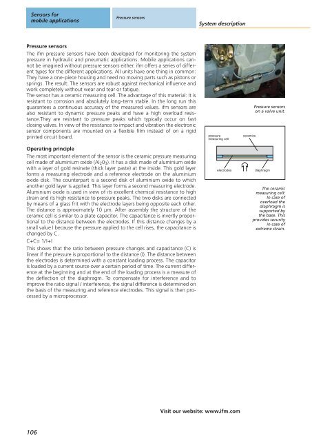
Sensors formobile applicationsPressure <strong>sensors</strong>System descriptionPressure <strong>sensors</strong>The ifm pressure <strong>sensors</strong> have been developed for monitoring the systempressure in hydraulic and pneumatic applications. Mobile applications cannotbe imagined without pressure <strong>sensors</strong> either. ifm offers a series of differenttypes for the different applications. All units have one thing in common:They have a one-piece housing and need no moving parts such as pistons orsprings. The result: The <strong>sensors</strong> are robust against mechanical influence andwork completely without wear and tear or fatigue.The sensor has a ceramic measuring cell. The advantage of this material: It isresistant to corrosion and absolutely long-term stable. In the long run thisguarantees a continuous accuracy of the measured values. ifm <strong>sensors</strong> arealso resistant to dynamic pressure peaks and have a high overload resistance.Theyare resistant to pressure peaks which typically occur on fastclosing valves. In view of the resistance to impact and vibration the electronicsensor components are mounted on a flexible film instead of on a rigidprinted circuit board.Operating principleThe most important element of the sensor is the ceramic pressure measuringcell made of aluminium oxide (Al 2 0 3 ). It has a disk made of aluminium oxidewith a layer of gold resinate (thick layer paste) at the inside. This gold layerforms a measuring electrode and a reference electrode on the aluminiumoxide disk. The counterpart is a second disk of aluminium oxide to whichanother gold layer is applied. This layer forms a second measuring electrode.Aluminium oxide is used in view of its excellent chemical resistance to highstrain and its high resistance to pressure peaks. The two disks are connectedby means of a glass frit with the electrode layers being opposite each other.The distance is approximately 10 μm. After assembly the structure of theceramic cell is similar to a plate capacitor. The capacitance is invertly proportionalto the distance between the electrodes. If this distance changes by asmall value I because the pressure applied to the cell rises, the capacitance ischanged by C.C+C= 1/I+IThis shows that the ratio between pressure changes and capacitance (C) islinear if the pressure is proportional to the distance (I). The distance betweenthe electrodes is determined with a constant loading process. The capacitoris loaded by a current source over a certain period of time. The current differenceat the beginning and at the end of the loading process is a measure ofthe deflection of the diaphragm. To compensate for interference and toimprove the ratio signal / interference, the signal difference is determined onthe basis of the measuring and reference electrodes. This signal is then processedby a microprocessor.pressuremeasuring cellelectrodesceramicsPressure <strong>sensors</strong>on a valve unit.diaphragmThe ceramicmeasuring cell:In case ofoverload thediaphragm issupported bythe base. Thisprovides securityin case ofextreme strain.Visit our website: www.ifm.com106