Inclination sensors
Inclination sensors
Inclination sensors
- No tags were found...

Create successful ePaper yourself
Turn your PDF publications into a flip-book with our unique Google optimized e-Paper software.
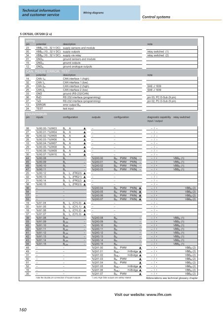
Technical informationand customer serviceWiring diagramsControl systems5 CR7020, CR7200 (2 x)wiringpin potential23 VBB S (10...32 V DC)05 VBB O (10...32 V DC)34 VBB R (10...32 V DC)01 GND S15 GND O12 GND Adescriptionsupply <strong>sensors</strong> and modulesupply outputssupply via relayground <strong>sensors</strong> and moduleground outputsground analogue outputsCAN, RS232, ERROR, TESTpin143226253306071324potentialCAN 1 HCAN 1 LCAN 2 HCAN 2 LGNDRxDTxDERRORTESTdescriptionCAN interface 1 (high)CAN interface 1 (low)CAN interface 2 (high)CAN interface 2 (low)ground (RS-232/CAN)RS 232 interface (programming)RS 232 interface (programming)error output B Htest inputinputs/outputspin inputsconfigurationoutputsconfigurationnoterelay switched (1)relay switched (2)noteSAE J 1939SAE J 1939pin 03, PC D-Sub (9 pin)pin 02, PC D-Sub (9 pin)diagnostic capabilityinput / outputrelay switched08270928102911304445464720022138365417531955183739034022414243044849315051521635%IX0.00 / %IW03%IX0.01 / %IW04%IX0.02 / %IW05%IX0.03 / %IW06%IX0.04 / %IW07%IX0.05 / %IW08%IX0.06 / %IW09%IX0.07 / %IW10%IX0.08%IX0.09%IX0.10%IX0.11%IX0.12%IX0.13%IX0.14%IX0.15––––%IX1.04%IX1.05%IX1.06%IX1.07%IX1.08%IX1.09%IX1.10%IX1.11%IX1.12%IX1.13%IX1.14%IX1.15––––––––B LB LB LB LB LB LB LB LB LB LB LB LB LB LB LB L––––B LB LB LB LB L/HB L/HB L/HB L/HB L/HB L/HB L/HB L/H––––––––AAAAAAAAI L (FRQ0)I L (FRQ1)I L (FRQ2)I L (FRQ3)I L (CYL0)I L (CYL1)I L (CYL2)I L (CYL3)note the double pin connection of inputs/outputs––––––––––––––––––––%QX0.00%QX0.01%QX0.02%QX0.03––––%QX0.04%QX0.05%QX0.06%QX0.07––––%QX0.08%QX0.09%QX0.10%QX0.11%QX0.12%QX0.13%QX0.14%QX0.15%QX1.00%QX1.01%QX1.02%QX1.03%QX1.04%QX1.05%QX1.06%QX1.07––––––––B H PWM PWM IB H PWM PWM IB H PWM PWM IB H PWM PWM I––––B H PWM PWM IB H PWM PWM IB H PWM PWM IB H PWM PWM I––––B HB HB HB HB HB HB HB HB H PWMB H/L* H-BridgeB H/L* H-BridgeB H PWMB H PWMB H/L* H-BridgeB H/L* H-BridgeB H PWM*) only High Side outputs are safety related––––––––––––– / –– / –– / –– / –– / –– / –– / –– / –– / •– / •– / •– / •– / –– / –– / –– / –– / •– / •– / •– / •– / –– / –– / –– / –– / •– / •– / •– / •– / •– / •– / •– / •– / •– / •– / •– / •– / •– / •– / •– / •VBB O (1)VBB O (1)VBB O (1)VBB O (1)VBB R (2)VBB R (2)VBB R (2)VBB R (2)VBB O (1)VBB O (1)VBB O (1)VBB O (1)VBB O (1)VBB O (1)VBB O (1)VBB O (1)VBB R (2)VBB R (2)VBB R (2)VBB R (2)VBB R (2)VBB R (2)VBB R (2)VBB R (2)Abbreviations see technical glossary chapterVisit our website: www.ifm.com160