- Page 1 and 2: Control systemsfor mobile vehiclesC
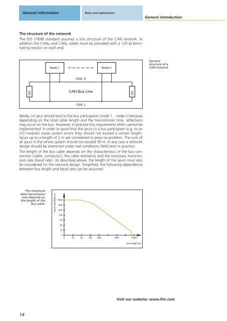
- Page 3: General informationNotes and explan
- Page 6 and 7: General informationNotes and explan
- Page 8 and 9: General informationNotes and explan
- Page 10 and 11: General informationNotes and explan
- Page 12 and 13: General informationNotes and explan
- Page 16 and 17: General informationNotes and explan
- Page 18 and 19: General informationNotes and explan
- Page 20 and 21: General informationNotes and explan
- Page 23 and 24: List of articlesOrder numbersin alp
- Page 25: Order numbersin alphanumeric orderO
- Page 28 and 29: Mobile controllersControllers and s
- Page 30 and 31: Mobile controllersControllers and s
- Page 32 and 33: Mobile controllersControllers and s
- Page 34 and 35: Mobile controllersControllers and s
- Page 36 and 37: Mobile controllersControllers and s
- Page 38 and 39: Mobile controllersControllers and s
- Page 40 and 41: Mobile controllersControllers and s
- Page 42 and 43: Mobile controllersControllers and s
- Page 44 and 45: Mobile controllersControllers and s
- Page 46 and 47: Mobile controllersControllers and s
- Page 48 and 49: Mobile controllersControllers and s
- Page 50 and 51: Mobile controllersControllers and s
- Page 53 and 54: I/O modulesTechnicalinformationand
- Page 55 and 56: I/O moduleswith CANopen interfaceCo
- Page 57 and 58: I/O moduleswith CANopen interfaceCa
- Page 59 and 60: I/O moduleswith CANopen interfaceTe
- Page 61 and 62: I/O moduleswith CANopen interfaceCo
- Page 63 and 64: I/O moduleswith CANopen interfaceSm
- Page 65 and 66:
I/O moduleswith CANopen interfaceCa
- Page 67:
I/O moduleswith CANopen interfaceKe
- Page 70 and 71:
Dialogue modulesDisplays, input mod
- Page 72 and 73:
Dialogue modulesDisplays, input mod
- Page 74 and 75:
Dialogue modulesDisplays, input mod
- Page 76 and 77:
Dialogue modulesDisplays, input mod
- Page 78 and 79:
Dialogue modulesDisplays, input mod
- Page 80 and 81:
Dialogue modulesDisplays, input mod
- Page 82 and 83:
Dialogue modulesDisplays, input mod
- Page 84 and 85:
Dialogue modulesDisplays, input mod
- Page 87 and 88:
Diagnosis and serviceTechnicalinfor
- Page 89 and 90:
Remote maintenance anddata memory,
- Page 91 and 92:
Remote maintenance anddata memory,
- Page 93 and 94:
Remote maintenance anddata memory,
- Page 95 and 96:
Remote maintenanceand data memoryCA
- Page 97 and 98:
Remote maintenanceand data memoryCA
- Page 99:
CAN interfaceand CAN diagnosisCANvi
- Page 102 and 103:
Sensors formobile applicationsIncli
- Page 104 and 105:
Sensors formobile applicationsInduc
- Page 106 and 107:
Sensors formobile applicationsPress
- Page 108 and 109:
Sensors formobile applicationsIncli
- Page 110 and 111:
Sensors formobile applicationsIncli
- Page 112 and 113:
Sensors formobile applicationsIncli
- Page 114 and 115:
Sensors formobile applicationsInduc
- Page 116 and 117:
Sensors formobile applicationsInduc
- Page 118 and 119:
Sensors formobile applicationsPress
- Page 121 and 122:
Signal convertersGeneralinformation
- Page 123 and 124:
Frequency, currentand voltage conve
- Page 125 and 126:
Frequency, currentand voltage conve
- Page 127:
Frequency, currentand voltage conve
- Page 130 and 131:
Connection technologyM12 connectors
- Page 132 and 133:
Connection technologyM12 connectors
- Page 134 and 135:
Connection technologyM12 connectors
- Page 136 and 137:
Connection technologyM12 connectors
- Page 139 and 140:
AccessoriesList of articlesGenerali
- Page 141 and 142:
Accessories for control systemsIllu
- Page 143 and 144:
Accessories for control systemsIllu
- Page 145 and 146:
Accessories for control systemsIllu
- Page 147 and 148:
Accessories for control systemsIllu
- Page 149 and 150:
Accessories for control systemsTech
- Page 151 and 152:
Accessories for control systemsIllu
- Page 153:
Technicalinformationand customerser
- Page 156 and 157:
Technical informationand customer s
- Page 158 and 159:
Technical informationand customer s
- Page 160 and 161:
Technical informationand customer s
- Page 162 and 163:
Technical informationand customer s
- Page 164 and 165:
Technical informationand customer s
- Page 166 and 167:
Technical informationand customer s
- Page 168 and 169:
Technical informationand customer s
- Page 170 and 171:
Technical informationand customer s
- Page 172 and 173:
Technical informationand customer s
- Page 174 and 175:
Technical informationand customer s
- Page 176 and 177:
Technical informationand customer s
- Page 178 and 179:
Technical informationand customer s
- Page 180 and 181:
Technical informationand customer s
- Page 182 and 183:
I/O modules1 type CR ....3969232272
- Page 184 and 185:
Technical informationand customer s
- Page 186 and 187:
Technical informationand customer s
- Page 188 and 189:
Technical informationand customer s
- Page 190 and 191:
Technical informationand customer s
- Page 192 and 193:
Technical informationand customer s
- Page 194 and 195:
Technical informationand customer s
- Page 196 and 197:
Technical informationand customer s
- Page 198 and 199:
Technical informationand customer s
- Page 200 and 201:
Technical informationand customer s
- Page 202 and 203:
Technical informationand customer s
- Page 204 and 205:
Technical informationand customer s
- Page 206 and 207:
Technical informationand customer s
- Page 208 and 209:
Technical informationand customer s
- Page 210 and 211:
Technical informationand customer s
- Page 212:
visit our website:www.ifm.comOvervi