MPX Series Video Encoders Front Panel - Teleste
MPX Series Video Encoders Front Panel - Teleste
MPX Series Video Encoders Front Panel - Teleste
- No tags were found...

Create successful ePaper yourself
Turn your PDF publications into a flip-book with our unique Google optimized e-Paper software.
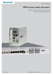
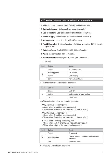
MPC series video encoders mechanical connections1. <strong>Video</strong> input(s) connector (BNC female) and indicator leds.2. Contact closure interfaces (4-pin screw terminal).*3. Led indicators. See tables below for detailed description.4. Power supply connector (2-pin screw terminal, +12 VDC).5. Management connection (CLI) (RJ-45 female).6. Fast Ethernet up-link interface (port A). Either electrical (RJ-45 female)or optical (LC).7. Data interfaces, EIA RS232/422/485 (RJ-45 female).8. Audio line connection (RJ-45 female).9. Fast Ethernet interface (port B), fi xed (RJ-45 female).** optionalLed Colour ModeTGreenBlinking greenYellowDarkPort confi guredOn streamLink missingPort not confi guredT - (terminal server) Led indicator operation.Led Colour ModeLGreenYellowDarkLink OKLink missing or level too lowNot in useL - (Ethernet network link) led indicator operationOnly A-port up and confi gured:- Green when A-port has cable connected- Yellow when A-port has not cable (B-port doesn’t affect)Only B-port up and confi gured:- Green when B-port has cable connected- Yellow when B-port has not cable (A-port doesn’t affect)Both A- and B- ports up and confi gured:- Green when both A- and B-ports has cable connected- Yellow when either of the cables is disconnectedLed Colour ModeMGreenBlinking greenRedPower ONDevice is being confi gured from the webinterfaceHardware errorM - (module) Led indicator operation.<strong>MPX</strong> series video encoders user manual 3