

XNX Universal Transmitter - Merkantile
XNX Universal Transmitter - Merkantile
XNX Universal Transmitter - Merkantile

You also want an ePaper? Increase the reach of your titles
YUMPU automatically turns print PDFs into web optimized ePapers that Google loves.
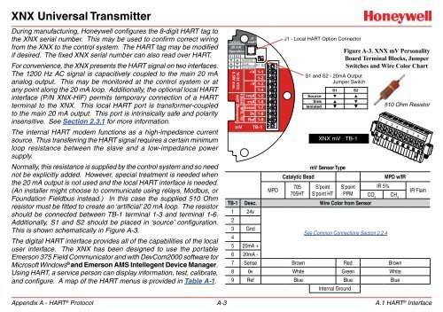
<strong>XNX</strong> <strong>Universal</strong> <strong>Transmitter</strong>During manufacturing, Honeywell configures the 8-digit HART tag tothe <strong>XNX</strong> serial number. This may be used to confirm correct wiringfrom the <strong>XNX</strong> to the control system. The HART tag may be modifiedif desired. The fixed <strong>XNX</strong> serial number can also read over HART.For convenience, the <strong>XNX</strong> presents the HART signal on two interfaces.The 1200 Hz AC signal is capacitively coupled to the main 20 mAanalog output. This may be monitored at the control system or atany point along the 20 mA loop. Additionally, the optional local HARTinterface (P/N <strong>XNX</strong>-HIF) permits temporary connection of a HARTterminal to the <strong>XNX</strong>. This local HART port is transformer-coupledto the main 20 mA output. This port is intrinsically safe and polarityinsensitive. See Section 2.3.1 for more information.The internal HART modem functions as a high-impedance currentsource. Thus transferring the HART signal requires a certain minimumloop resistance between the slave and a low-impedance powersupply.Normally, this resistance is supplied by the control system and so neednot be explicitly added. However, special treatment is needed whenthe 20 mA output is not used and the local HART interface is needed.(An installer might choose to communicate using relays, Modbus, orFoundation Fieldbus instead.) In this case the supplied 510 Ohmresistor must be fitted to create an ‘artificial’ 20 mA loop. The resistorshould be connected between TB-1 terminal 1-3 and terminal 1-6.Additionally, S1 and S2 should be placed in ‘source’ configuration.This is shown schematically in Figure A-3.The digital HART interface provides all of the capabilities of the localuser interface. The <strong>XNX</strong> has been designed to use the portableEmerson 375 Field Communicator and with DevCom2000 software forMicrosoft Windows ® and Emerson AMS Intellegent Device Manager.Using HART, a service person can display information, test, calibrate,and configure. A map of the HART menus is provided in Table A-1.Appendix A - HART ® Protocol A-3LOCAL20 mAOperationS1 S216-32 VDC6.5W max.4-20mA MPD, 705HART SensepointmVJ1HARTSourceSink S1 S2Isolated+V 1-11-2-V 1-31-4+mA 1-5-mA 1-6Sense 1-70v 1-8Ref 1-9TB-1MPDJ1 - Local HART Option ConnectorS1 and S2 - 20mA OutputJumper SwitchSourceSinkIsolatedCatalytic Bead705705HTS1▼▲▼<strong>XNX</strong> mV TB-1mV Sensor TypeS’pointS’point HTFigure A-3. <strong>XNX</strong> mV PersonalityBoard Terminal Blocks, JumperSwitches and Wire Color ChartS’pointPPMS2▲▼▼TB-1 Desc. Wire Color from Sensor1 24vIR 5%MPD w/IRCO 2CH 423 Gnd4See Common Connections Section 2.2.45 20mA +6 20mA -7 Sense Brown Red Brown8 0v White Green White9 Ref Blue Blue BlueInternal Ground510 Ohm Resistor1 2 3 4 5 6 7 8 9IR FlamA.1 HART ® Interface


