

XNX Universal Transmitter - Merkantile
XNX Universal Transmitter - Merkantile
XNX Universal Transmitter - Merkantile

You also want an ePaper? Increase the reach of your titles
YUMPU automatically turns print PDFs into web optimized ePapers that Google loves.
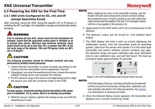
<strong>XNX</strong> <strong>Universal</strong> <strong>Transmitter</strong>2.4 Powering the <strong>XNX</strong> for the First Time2.4.1 <strong>XNX</strong> Units Configured for EC, mV, and IR(except Searchline Excel)After mounting, wiring the <strong>XNX</strong>, wiring the specific mV or IR sensor orinstalling the EC cartridge, the installation visually and electrically testedas below.WARNINGPrior to carrying out any work, ensure local and site procedures arefollowed. Ensure that the associated control panel is inhibited so asto prevent false alarms. Minimum and maximum controller alarmlevels should not be set at less than 10% or greater than 90% of thefull scale range of the detector. CSA and FM agency limits are 60%LEL or 0.6mg/m 3 .CautionThe following procedure should be followed carefully and onlyperformed by suitably trained personnel1. Check that the transmitter is wired correctly according to thismanual and the associated control equipment manual.2. If equipped, unscrew the weatherproof cover, loosen the sensorretainer locking screw and unscrew the retainer.3. For EC sensors, plug in the sensor cartridge taking care to alignthe sensor pins with the connector holes in the PCB.CautionFor toxic sensors, remove the shorting clip from the bottom of the sensorprior to installation. For O 2sensor, there is no shorting clip provided.4. Refit the sensor retainer, tighten the locking screw and refit theweatherproof cover.Note:Before replacing the cover on the transmitter housing, coat thethreads with anti-seize compound to prevent corrosion buildup.Also inspect the cover o-ring for cracking or any other defect thatmight compromise the integrity of the seal. If it is damaged, replacewith the o-ring supplied in the accessory kit.5. Apply power to the <strong>XNX</strong> which will in turn provide power to thedetector.6. The detector output will be forced to 1mA (default fault/inhibit).7. The <strong>XNX</strong> display will enter a start up routine displaying theinitialization screen, then the transmitter loads its operatingsystem, data from the sensor and checks if it is the same typetransmitter and sensor software version numbers, gas type,the detection range and span calibration gas level, estimatedtime to next calibration due, and self test result. The boot-upprocedure takes approximately 45 seconds.Figure 2-29. <strong>XNX</strong> Initialization and General Status ScreensNote:In the final stages of boot-up, warnings and faults may be observeduntil the user performs the proper configuration, calibration, andreset activities described in the following sections. See Section5 for descriptions of warnings and faults.8. Once the General Status screen appears, the transmitter anddetector are in normal ‘monitoring’ mode.Section 2 - Installation and Operation 2-272.4 Powering the <strong>XNX</strong> for the First Time


