GPS-NAVIGATOR GP-32 & GP-37
GPS-NAVIGATOR GP-32 & GP-37
GPS-NAVIGATOR GP-32 & GP-37

Create successful ePaper yourself
Turn your PDF publications into a flip-book with our unique Google optimized e-Paper software.
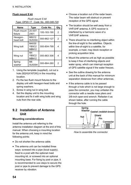
9. INSTALLATIONFlush mount S kitFlush mount S kitType: OP20-17 Code No. 000-040-720Name Type Code No. QtyFlush mountfixtureHexagonheadboltWing boltWing nutSpringwasher20-007-2401M6X12SUS304M4X30YBSC2MBN12M4YBSC2MBN12M6SUS304100-183-190 2000-862-127 2000-804-799 4000-863-306 4000-864-260 21. Using the template (supplied), cut out ahole (92(H)X167(W)) in the mountinglocation.2. Fix the two flush mount fixtures to thedisplay unit with hexagon-head bolts andspring washers.3. Screw in wing nut in wing bolt.4. Set the display unit to the mountinglocation and fix it with wing bolts and wingnuts from the rear side.• Choose a location out of the radar beam.The radar beam will obstruct or preventreception of the <strong><strong>GP</strong>S</strong> signal.• The location should be well away from aVHF/UHF antenna. A <strong><strong>GP</strong>S</strong> receiver isinterfered by a harmonic wave of aVHF/UHF antenna.• There should be no interfering object withinthe line-of-sight to the satellites. Objectswithin line-of-sight to a satellite, forexample, a mast, may block reception orprolong acquisition time.• Mount the antenna unit as high as possibleto keep it free of interfering objects andwater spray, which can interrupt receptionof <strong><strong>GP</strong>S</strong> satellite signal if the water freezes.• See the outline drawing for the antennaunit at the back of this manual for minimumseparation distances from other antennas.• If the antenna cable is to be passedthrough a hole which is not large enough topass the connector, you may unfasten theconnector with a needle nose pliers and3/8-inch open-end wrench. Refasten it asshown below, after running the cablethrough the hole.9.2 Installation of AntennaUnitMounting considerationsInstall the antenna unit referring to theantenna installation diagram at the end of thismanual. When choosing a mounting locationfor the antenna unit, keep in mind thefollowing points:How to assemble the connector• Do not shorten the antenna cable.• The antenna unit can be installed threeways: screwed into a pipe (local supply),fixed to a post with the optional mastmounting kit, or screwed into an optionalmounting base. For fixing by post or pipe, itis recommended to use stays to secure thepost or pipe to prevent damage to the <strong><strong>GP</strong>S</strong>receiver by vibration.54