- Page 1 and 2:
1 C-POWER : C Range Page CE marked
- Page 3 and 4:
1 Rating (A) 400 630 800 Type Desig
- Page 5 and 6:
1 Rating (A) 1600 2000 2500 Type De
- Page 7 and 8:
1 1/6 SR21 SR21E Note : 3 phase, 4
- Page 9 and 10:
1 1/8 Type of Protection PROTECTION
- Page 11 and 12:
1 1/10 ZONE SELECTIVE INTERLOCKING
- Page 13 and 14:
1 1/12 PROTECTION SOLID STATE CHARA
- Page 15 and 16:
1 * Not recommended 1/14 PROTECTION
- Page 17 and 18:
1 1/16 ACCESSORIES ACB tripping ind
- Page 19 and 20:
1 OPERATION COUNTER SRT - 2 for SR2
- Page 21 and 22:
1 All Air Circuit Breakers conform
- Page 23 and 24:
1 Terminal Orientation* Straight Ho
- Page 25 and 26:
1 �or 800 A to 2500 A 3P/4P 1/24
- Page 27 and 28:
1 �or 630A - 2000A 3P Note : All
- Page 29 and 30:
1 �LAT TERMINAL CONNECTIONS 1/28
- Page 31 and 32:
1 1/30 OVERALL DIMENSIONS - TYPE H
- Page 33 and 34:
1 �OR �IXED ACBs - 800A to 4000
- Page 35 and 36:
1 �OR DRAWOUT ACBs - 3200 D, 4000
- Page 37 and 38:
1 1/36 SPRING CHARGE INDICATION (
- Page 39 and 40:
2 DS Page �ixed Overload & �ixe
- Page 41 and 42:
2 2/1 MOULDED CASE CIRCUIT BREAKERS
- Page 43 and 44:
2 Note : �or ordering information
- Page 45 and 46:
2 Note : �or ordering information
- Page 47 and 48:
2 Auxiliary Contacts 2/7 ACCESSORIE
- Page 49 and 50:
2 2/9 TECHNICAL DATA - DS Type Desi
- Page 51 and 52:
2 2/11 TECHNICAL DATA - DTH...E Typ
- Page 53 and 54:
2 2/13 TECHNICAL DATA - DH Type Des
- Page 55 and 56:
2 2/15 TECHNICAL DATA - DL Type Des
- Page 57 and 58:
2 2/17 TECHNICAL DATA - DTH Type De
- Page 59 and 60:
2 2/19 TECHNICAL DATA - DX..S (3/4
- Page 61 and 62:
2 2/21 TECHNICAL DATA - DX..H (3/4
- Page 63 and 64:
2 2/23 TECHNICAL DATA - DM Type Des
- Page 65 and 66:
2 2/25 TECHNICAL DATA - D� Type D
- Page 67 and 68:
2 2/27 I-t CHARACTERISTIC CURVES MC
- Page 69 and 70:
2 2/29 I-t CHARACTERISTIC CURVES MC
- Page 71 and 72:
2 2/31 I-t CHARACTERISTIC CURVES MC
- Page 73 and 74:
2 2/33 125 250 I-t CHARACTERISTIC C
- Page 75 and 76:
2 2/35 I-t CHARACTERISTIC CURVES DX
- Page 77 and 78:
2 2/37 ORDERING DATA - DG RANGE MCC
- Page 79 and 80:
2 2/39 ORDERING DATA - DL RANGE MCC
- Page 81 and 82:
2 2/41 ORDERING DATA - DX..S (3 POL
- Page 83 and 84:
2 2/43 ORDERING DATA - DM RANGE MCC
- Page 85 and 86:
2 Accessory Coil Voltage / Location
- Page 87 and 88:
2 Accessory Coil Voltage / Location
- Page 89 and 90:
2 2/49 ACCESSORIES - ORDERING DATA
- Page 91 and 92:
2 Accessory Type Std. Pack Catalgou
- Page 93 and 94:
2 Accessory Type Std. Pack Catalgou
- Page 95 and 96:
2 Accessory Coil Voltage / Location
- Page 97 and 98:
2 2/57 OVERALL DIMENSIONS DIMENSION
- Page 99 and 100:
2 Note: All dimensions are in mm. 2
- Page 101 and 102:
2 Note: All dimensions are in mm. 2
- Page 103 and 104:
2 Note: All dimensions are in mm. 2
- Page 105 and 106:
2 Note: All dimensions are in mm. 2
- Page 107 and 108:
2 Note: All dimensions are in mm. 2
- Page 109 and 110:
2 Note: All dimensions are in mm. 2
- Page 111 and 112:
2 Note: All dimensions are in mm. 2
- Page 113 and 114:
2 Note: All dimensions are in mm. 2
- Page 115 and 116:
2 Note: All dimensions are in mm. 2
- Page 117 and 118:
2 2/77 OVERALL DIMENSIONS ROTARY OP
- Page 119 and 120:
2 2/79 OVERALL DIMENSIONS & CONNECT
- Page 121 and 122:
2 2/81 WIRING DIAGRAM EARTH �AULT
- Page 123 and 124:
3 SWITCH DISCONNECTOR �USE SD�
- Page 125 and 126:
3 3/1 Wide Range of SD�s suitable
- Page 127 and 128:
3 Sheet-steel Enclosure 3/3 SHEET S
- Page 129 and 130:
3 3/5 Conformance to IS 13947 (Part
- Page 131 and 132:
3 ORDERING IN�ORMATION: Ordering
- Page 133 and 134:
3 3/9 Conformance to IS 13947 (Part
- Page 135 and 136:
3 3/11 Conformance to IS 13947 (Par
- Page 137 and 138:
3 3/13 WIDE RANGE O� SWITCH DISCO
- Page 139 and 140:
3 3/15 Conformance to IS 13947 (Par
- Page 141 and 142:
3 ORDERING IN�ORMATION: Ordering
- Page 143 and 144:
3 3/19 ACCESSORIES �OR �N RANGE
- Page 145 and 146:
3 3/21 SELECTION TABLE �OR HANDLE
- Page 147 and 148:
3 �our breaking points per pole w
- Page 149 and 150:
3 3/25 ACCESSORIES �OR CHANGEOVER
- Page 151 and 152:
3 3/27 B 02, STANDARD REAR MOUNTING
- Page 153 and 154:
3 AC SWITCHES (SERIES S, SG & TP) A
- Page 155 and 156:
3 The switches of S, TP, SG & RT ty
- Page 157 and 158:
3 AC SWITCHES (SERIES-S,SG,RT & TP)
- Page 159 and 160:
3 B 33, ROUND PADLOCK Switches are
- Page 161 and 162:
3 B 41, DOOR CLUTCH These switches
- Page 163 and 164:
3 B 51, KEY OPERATED Switches suita
- Page 165 and 166:
3 B 19, STANDARD 22.5 Switches with
- Page 167 and 168:
3 Other size mounting plates at fro
- Page 169 and 170:
3 SG-TYPE RECTANGULAR S-TYPE STAGE
- Page 171 and 172:
3 ISOLATORS 60 o (ON-OFF SWITCHES)
- Page 173 and 174:
3 ISOLATORS 45o SPRING RETURN (ON-O
- Page 175 and 176:
3 CHANGE OVER SWTICHES 90 o (DOUBLE
- Page 177 and 178:
3 MULTI STEP SWITCHES - 60 O (POLE
- Page 179 and 180:
3 MULTI STEP SWTICHES - 45 o (POLE
- Page 181 and 182: 3 AMMETER SELCTOR SWITCHES...Contd
- Page 183 and 184: 3 MOTOR SWITCHES (AC3) STAR DELTA S
- Page 185 and 186: 3 CONTROL SWITCHES 3/61 SCRIPT PROG
- Page 187 and 188: 3 Example While placing the order,
- Page 189 and 190: 3 3/65 ORDERING IN�ORMATION CUSTO
- Page 191 and 192: 3 Note: All dimensions are in mm. 3
- Page 193 and 194: 3 Note: All dimensions are in mm. 3
- Page 195 and 196: 3 3/71 Extreme overall dimensions O
- Page 197 and 198: 3 3/73 OVERALL DIMENSIONS SWITCH-DI
- Page 199 and 200: 3 3/75 OVERALL DIMENSIONS SWITCH-DI
- Page 201 and 202: 3 3/77 OVERALL DIMENSIONS SWITCH DI
- Page 203 and 204: 3 Note: All dimensions are in mm. 3
- Page 205 and 206: 4 HIGH RUPTURING CAPACITY �USE (H
- Page 207 and 208: 4 4/2 TECHNICAL DATA & ORDERING IN
- Page 209 and 210: 4 4/4 WIDE RANGE O� BS TYPE �US
- Page 211 and 212: 4 4/6 TECHNICAL DATA & ORDERING IN
- Page 213 and 214: 4 Note: All dimensions are in mm. 4
- Page 215 and 216: 4 4/10 PRE-ARCING TIME (SECONDS) CU
- Page 217 and 218: 5 Over Current Relays Page Types -
- Page 219 and 220: 5 Other Relays Page Types - MX7/5,
- Page 221 and 222: 5 5/2 TECHNICAL DATA THREE PHASE OV
- Page 223 and 224: 5 5/4 ORDERING IN�ORMATION THREE
- Page 225 and 226: 5 5/6 WIRING DIAGRAM CURRENT SENSIN
- Page 227 and 228: 5 ✦ Easy Setting through front pa
- Page 229 and 230: 5 5/10 ORDERING IN�ORMATION NEUTR
- Page 231: 5 5/12 WIRING DIAGRAM SECONDARY REL
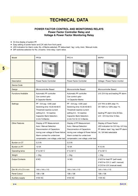
- Page 235 and 236: 5 5/16 ORDERING IN�ORMATION POWER
- Page 237 and 238: 5 5/18 WIRING DIAGRAM MOTOR PROTECT
- Page 239 and 240: 5 5/20 TECHNICAL DATA GENERATOR PRO
- Page 241 and 242: 5 5/22 ORDERING IN�ORMATION GENER
- Page 243 and 244: 5 5/24 WIRING DIAGRAM SYNCHRONISING
- Page 245 and 246: 5 5/26 TECHNICAL DATA VOLTAGE / �
- Page 247 and 248: 5 5/28 ORDERING IN�ORMATION VOLTA
- Page 249 and 250: 5 5/30 WIRING DIAGRAM TRANS�ORMER
- Page 251 and 252: 5 5/32 TECHNICAL DATA CONTROL & SUP
- Page 253 and 254: 5 5/34 ORDERING IN�ORMATION CONTR
- Page 255 and 256: 5 5/36 WIRING DIAGRAM REVERSE POWER
- Page 257 and 258: 6 MN9 to MN32 Page General Informat
- Page 259 and 260: 6 6/1 SALIENT �EATURES O� MN CO
- Page 261 and 262: 6 6/3 Conformance to IS 13947 (Part
- Page 263 and 264: 6 Mechanical �or Contactor type Q
- Page 265 and 266: 6 6/7 Catalogue No. suffixes for ra
- Page 267 and 268: 6 Auxiliary Contact Block Ie Ie Aux
- Page 269 and 270: 6 6/11 Catalogue No. suffixes for r
- Page 271 and 272: 6 Auxiliary Contact Block Ie Ie Aux
- Page 273 and 274: 6 6/15 Catalogue No. suffixes for r
- Page 275 and 276: 6 6/17 MN45 MN65 Mechanical Life Op
- Page 277 and 278: 6 6/19 MN185 MN225 Mechanical Life
- Page 279 and 280: 6 6/21 MN9W MN12W MN16W MN25W Mecha
- Page 281 and 282: 6 6/23 ML0 ML1 ML1.5 ML2 ML3 Mechan
- Page 283 and 284:
6 6/25 MM00-AC MM01-AC MM00-DC MM01
- Page 285 and 286:
6 6/27 ELECTRICAL LI�E CURVES - T
- Page 287 and 288:
6 6/29 ELECTRICAL LI�E CURVES - T
- Page 289 and 290:
6 6/31 TERMINAL ARRANGEMENTS - TYPE
- Page 291 and 292:
6 6/33 TERMINAL ARRANGEMENTS CONTRO
- Page 293 and 294:
6 Note: All dimensions are in mm. 6
- Page 295 and 296:
6 Note: All dimensions are in mm. 6
- Page 297 and 298:
6 Note: All dimensions are in mm. 6
- Page 299 and 300:
6 Note: All dimensions are in mm. 6
- Page 301 and 302:
7 THERMAL OVERLOAD RELAYS MN1 to MN
- Page 303 and 304:
7 MN12 MN12L 7/2 THERMAL OVERLOAD R
- Page 305 and 306:
7 7/4 �or Contactor Setting Wt Qt
- Page 307 and 308:
7 TECHNICAL DATA �OR THERMAL OVER
- Page 309 and 310:
7 7/8 I-T CHARACTERISTICS 3 POLE BA
- Page 311 and 312:
7 Note: All dimensions are in mm. 7
- Page 313 and 314:
8 MN16 to MN65 Page 3-phase control
- Page 315 and 316:
8 MA25 Page 3-phase control upto 30
- Page 317 and 318:
8 MN16 MN25 8/2 DIRECT-ON-LINE STAR
- Page 319 and 320:
8 ✦ Both �ASD and SASD version
- Page 321 and 322:
8 ✦ Only �ASD version available
- Page 323 and 324:
8 Catalogue No. suffixes for rated
- Page 325 and 326:
8 MA25SASD/�ASD 8/10 STAR-DELTA S
- Page 327 and 328:
8 ML3 8/12 DIRECT-ON-LINE STARTER -
- Page 329 and 330:
8 ✦ Single phase and overload pro
- Page 331 and 332:
8 Catalogue No. suffixes for rated
- Page 333 and 334:
8 Catalogue No. suffixes for rated
- Page 335 and 336:
8 Catalogue No. suffixes for rated
- Page 337 and 338:
8 MK1 8/22 STAR-DELTA STARTERS - TY
- Page 339 and 340:
8 Catalogue No. suffixes for rated
- Page 341 and 342:
8 Sr.No. 1 0.125 0.09 0.4 0.3 - 0.5
- Page 343 and 344:
8 Sr. No. 1 1 0.75 2.1 1.21 0.9 - 1
- Page 345 and 346:
8 Sr. No. 1 1 0.75 1.8 1.04 1 - 1.6
- Page 347 and 348:
8 1 0.05 0.04 0.75 0.15 - 0.25 2 A
- Page 349 and 350:
8 Note: All dimensions are in mm. 8
- Page 351 and 352:
8 Note: All dimensions are in mm. 8
- Page 353 and 354:
8 8/38 MN16 �ASD MN25, MN32 �AS
- Page 355 and 356:
8 8/40 WIRING DETAILS MA25 �ASD M
- Page 357 and 358:
8 8/42 ML2 �ASD ML3 �ASD WIRING
- Page 359 and 360:
8 8/44 M�1 DOL (3 PHASE) STARTERS
- Page 361 and 362:
9 Cable Ducts Page Product Data - T
- Page 363 and 364:
9 ✦ Manufactured from specially c
- Page 365 and 366:
9 S.No. Channel with Cover Width x
- Page 367 and 368:
9 9/5 ORDERING DATA - TYPE B Descri
- Page 369 and 370:
9 9/7 SALIENT �EATURES O� LIMIT
- Page 371 and 372:
9 PC 600 SERIES SNAP PUSH ROD OPERA
- Page 373 and 374:
9 PC 1000 SERIES SNAP WITH 1.2 KG P
- Page 375 and 376:
9 9/13 TECHNICAL DATA LIMIT SWITCHE
- Page 377 and 378:
9 9/15 ORDERING DATA Description Ca
- Page 379 and 380:
9 9/17 SALIENT �EATURES O� TIME
- Page 381 and 382:
9 9/19 ACCESSORIES Accessory Type D
- Page 383 and 384:
9 9/21 RANGE AND ORDERING DATA ELEC
- Page 385 and 386:
9 9/23 TECHNICAL DATA ELECTRONIC TI
- Page 387 and 388:
9 Type 9/25 TECHNICAL DATA HOUR MET
- Page 389 and 390:
9 ✦ Elegant and light weight. ✦
- Page 391 and 392:
9 9/29 RANGE AND ORDERING DATA SELE
- Page 393 and 394:
9 9/31 LENS CAP Colour SPARES Catal
- Page 395 and 396:
9 BA 9S type 9/33 ACCESSORIES �IL
- Page 397 and 398:
9 9/35 RANGE AND ORDERING DATA PUSH
- Page 399 and 400:
9 9/37 GENERAL PURPOSE ENCLOSURES P
- Page 401 and 402:
9 9/39 RANGE AND ORDERING DATA PUSH
- Page 403 and 404:
9 9/41 TECHNICAL DATA Rated Voltage
- Page 405 and 406:
9 Note: All dimensions are in mm. 9
- Page 407 and 408:
9 Note: All dimensions are in mm. 9
- Page 409 and 410:
9 9/47 PC�S-1 COMPACT TYPE Note:
- Page 411 and 412:
9 Note: All dimensions are in mm. 9
- Page 413 and 414:
9 Note: All dimensions are in mm. 9
- Page 415 and 416:
9 9/53 Description L P Note: All di
- Page 417 and 418:
11 11/1 INTRODUCTION : MOTOR PROTEC
- Page 419 and 420:
11 Rated current (A) 11/3 SELECTION
- Page 421 and 422:
11 Number of poles 3 3 Max. rated c
- Page 423 and 424:
11 11/7 I-t CHARACTERISTICS - MG1
- Page 425 and 426:
11 Note: All dimensions are in mm.
- Page 427 and 428:
12 Series 26 D 19 M Type MPP-D MPP-
- Page 429 and 430:
12 Series 16 � 20 � Type MD �
- Page 431 and 432:
12 OVERALL DIMENSIONS - SERIES 19 M
- Page 433 and 434:
12 OVERALL DIMENSIONS - SERIES 61 M
- Page 435 and 436:
12 Output, Qn kVAr 10 13.91 20�31
- Page 437 and 438:
12 Output, Qn kVAr 30 15+15 41.78 1
- Page 439 and 440:
12 Output, Qn kVAr 45 15 x 3 62.68
- Page 441 and 442:
12 Output, Qn kVAr 80 20 x 4 111.43
- Page 443 and 444:
✦ Current Reversal Indication ✦
- Page 445 and 446:
Accuracy Class 1.0 - IEC 1036 / IS
- Page 447 and 448:
PRODUCT HIGHLIGHTS DISPLAY PARAMETE
- Page 449 and 450:
ORDERING IN�ORMATION ELECTRONIC E
- Page 451 and 452:
Note: All dimensions are in mm. OVE
- Page 453 and 454:
Note: All dimensions are in mm. PAN
- Page 455 and 456:
DISTRIBUTION BOARDS & ENCLOSURES 30
- Page 457 and 458:
DISTRIBUTION BOARDS & ENCLOSURES co
- Page 459 and 460:
NEW PROTECTION DEVICES miniature ci
- Page 461 and 462:
NEW AUTOMATION & CONTROL DEVICES is
- Page 463 and 464:
NEW AUTOMATION & CONTROL DEVICES th
- Page 465 and 466:
volta enclosures IP30 insulated flu
- Page 467 and 468:
miniature circuit breakers - Type N
- Page 469 and 470:
esidual current circuit breakers (R
- Page 471 and 472:
PROTECTION DEVICES, AUTOMATION & CO
- Page 473 and 474:
twilight switch The switch measures
- Page 475 and 476:
thermostats These devices can be us
- Page 477 and 478:
16A plug & socket board with SP MCB
- Page 479 and 480:
INDVICTA RANGE DIMENSIONS Indvicta
- Page 481 and 482:
SYSTEM BUILDING WITH INDVICTA DISTR
- Page 483 and 484:
Cosmos Phase changeover universal d
- Page 485 and 486:
Data Communication Components Page
- Page 487 and 488:
BUS US ENCLOSURE ENCLOSURE BG BG (P
- Page 489 and 490:
COMP COMPACT COMP CT ENCLOSURE ENCL
- Page 491 and 492:
COMP COMPACT COMP CT ENCLOSURES ENC
- Page 493 and 494:
MODULE MODULE COMBI COMBI SYSTEM SY
- Page 495 and 496:
EX EX ENCLOSURES ENCLOSURES KEL KEL
- Page 497 and 498:
482.6 482.6 MM MM (19") (19") SUBRA
- Page 499 and 500:
METRIC METRIC SUBRA SUBRACK SUBRA C
- Page 501 and 502:
SUBRA SUBRACKS/CASES SUBRA CKS/CASE
- Page 503 and 504:
RITT RITTAL RITT AL ELECTR ELECTRON
- Page 505 and 506:
RITT RITTAL RITT AL VARIO-RA ARIO-R
- Page 507 and 508:
WALL ALL MOUNTED MOUNTED COOLING CO
- Page 509 and 510:
AIR/W AIR/WATER AIR/W TER HEA HEAT
- Page 511 and 512:
RA RACK-MOUNTED RA CK-MOUNTED F FFA
- Page 513 and 514:
Bar thickness (cross-section) PLS 8
- Page 515 and 516:
* AWG = American Wire Gauges AWG 10
- Page 517 and 518:
DK DK NETW NETWORK NETW ORK ENCLOSU
- Page 519 and 520:
DK DK NETW NETWORK NETW ORK ENCLOSU
- Page 521 and 522:
DK DK SMALL SMALL FIBRE-OPTIC FIBRE
- Page 523 and 524:
FM FM WALL-MOUNTED ALL-MOUNTED DIST
- Page 525 and 526:
CS CS OUTDOOR OUTDOOR MODULAR MODUL
- Page 527 and 528:
SALIENT �EATURES O� INDICATING
- Page 529 and 530:
ACCESSORIES Accessory Type Catalogu
- Page 531 and 532:
DC Voltmeters DC Ammeters RC. MOVIN
- Page 533 and 534:
Special DC Meters RD. SPECIAL DC ME
- Page 535:
TECHNICAL DATA Type of Moving iron