

mag

You also want an ePaper? Increase the reach of your titles
YUMPU automatically turns print PDFs into web optimized ePapers that Google loves.
Malaysia Water Research Journal<br />
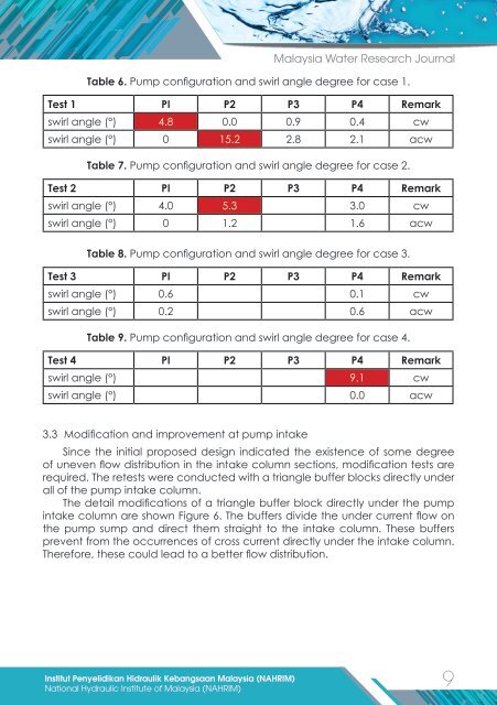
Table 6. Pump configuration and swirl angle degree for case 1.<br />
Test 1 PI P2 P3 P4 Remark<br />
swirl angle (°) 4.8 0.0 0.9 0.4 cw<br />
swirl angle (°) 0 15.2 2.8 2.1 acw<br />
Table 7. Pump configuration and swirl angle degree for case 2.<br />
Test 2 PI P2 P3 P4 Remark<br />
swirl angle (°) 4.0 5.3 3.0 cw<br />
swirl angle (°) 0 1.2 1.6 acw<br />
Table 8. Pump configuration and swirl angle degree for case 3.<br />
Test 3 PI P2 P3 P4 Remark<br />
swirl angle (°) 0.6 0.1 cw<br />
swirl angle (°) 0.2 0.6 acw<br />
Table 9. Pump configuration and swirl angle degree for case 4.<br />
Test 4 PI P2 P3 P4 Remark<br />
swirl angle (°) 9.1 cw<br />
swirl angle (°) 0.0 acw<br />
3.3 Modification and improvement at pump intake<br />
Since the initial proposed design indicated the existence of some degree<br />
of uneven flow distribution in the intake column sections, modification tests are<br />
required. The retests were conducted with a triangle buffer blocks directly under<br />
all of the pump intake column.<br />
The detail modifications of a triangle buffer block directly under the pump<br />
intake column are shown Figure 6. The buffers divide the under current flow on<br />
the pump sump and direct them straight to the intake column. These buffers<br />
prevent from the occurrences of cross current directly under the intake column.<br />
Therefore, these could lead to a better flow distribution.<br />
Institut Penyelidikan Hidraulik Kebangsaan Malaysia (NAHRIM)<br />
9<br />
National Hydraulic Institute of Malaysia (NAHRIM)