

mag

You also want an ePaper? Increase the reach of your titles
YUMPU automatically turns print PDFs into web optimized ePapers that Google loves.
Malaysia Water Research Journal<br />
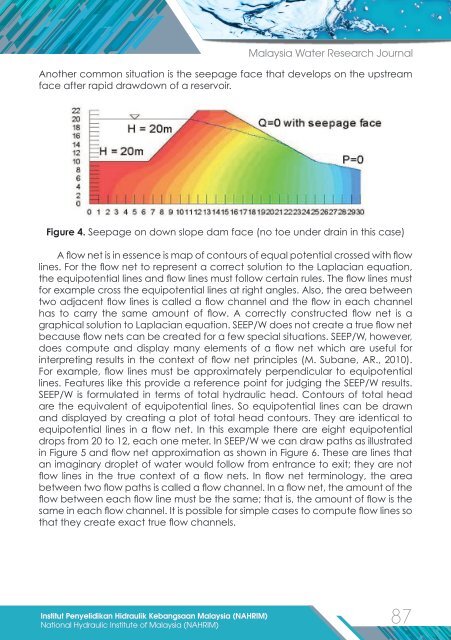
Another common situation is the seepage face that develops on the upstream<br />
face after rapid drawdown of a reservoir.<br />
Figure 4. Seepage on down slope dam face (no toe under drain in this case)<br />
A flow net is in essence is map of contours of equal potential crossed with flow<br />
lines. For the flow net to represent a correct solution to the Laplacian equation,<br />
the equipotential lines and flow lines must follow certain rules. The flow lines must<br />
for example cross the equipotential lines at right angles. Also, the area between<br />
two adjacent flow lines is called a flow channel and the flow in each channel<br />
has to carry the same amount of flow. A correctly constructed flow net is a<br />
graphical solution to Laplacian equation. SEEP/W does not create a true flow net<br />
because flow nets can be created for a few special situations. SEEP/W, however,<br />
does compute and display many elements of a flow net which are useful for<br />
interpreting results in the context of flow net principles (M. Subane, AR., 2010).<br />
For example, flow lines must be approximately perpendicular to equipotential<br />
lines. Features like this provide a reference point for judging the SEEP/W results.<br />
SEEP/W is formulated in terms of total hydraulic head. Contours of total head<br />
are the equivalent of equipotential lines. So equipotential lines can be drawn<br />
and displayed by creating a plot of total head contours. They are identical to<br />
equipotential lines in a flow net. In this example there are eight equipotential<br />
drops from 20 to 12, each one meter. In SEEP/W we can draw paths as illustrated<br />
in Figure 5 and flow net approximation as shown in Figure 6. These are lines that<br />
an i<strong>mag</strong>inary droplet of water would follow from entrance to exit; they are not<br />
flow lines in the true context of a flow nets. In flow net terminology, the area<br />
between two flow paths is called a flow channel. In a flow net, the amount of the<br />
flow between each flow line must be the same; that is, the amount of flow is the<br />
same in each flow channel. It is possible for simple cases to compute flow lines so<br />
that they create exact true flow channels.<br />
Institut Penyelidikan Hidraulik Kebangsaan Malaysia (NAHRIM)<br />
87<br />
National Hydraulic Institute of Malaysia (NAHRIM)