atw - International Journal for Nuclear Power | 04.2019

You also want an ePaper? Increase the reach of your titles
YUMPU automatically turns print PDFs into web optimized ePapers that Google loves.
<strong>atw</strong> Vol. 64 (2019) | Issue 4 ı April<br />
(22)<br />
In this equation, the square root of<br />
the semi-length is eliminated. In this<br />
way, it is independent of the geometry,<br />
as the strip model. In order to<br />
use an adimesional <strong>for</strong>m, the following<br />
parameters have to be established.<br />
and<br />
The new equation is<br />
(23)<br />
This curve is the boundary between<br />
the safe and unsafe zones (Fig. 9).<br />
Fracture would take place when the<br />
Effective Stress Intensity Factor is<br />
bigger than the Fracture Toughness,<br />
K r > 1 On the other hand, ductile<br />
failure is expected if S r > 1. Also, it is<br />
important to observe that in the<br />
elastoplastic analysis, fracture and<br />
collapse are in interaction. The points<br />
defined by K r and S r have to be<br />
localized in the failure diagram so as<br />
to determine if they are in the safe or<br />
unsafe zones.<br />
The material hardening has not<br />
been considered in the “Strip-Yield”<br />
model. There<strong>for</strong>e, this situation<br />
can be included in an elastoplastic<br />
analysis with the J-integral. The<br />
equation proposed by the British<br />
Standard BS 7910 is<br />
(24)<br />
The Failure Diagram shown in Figure<br />
11 compares different failure<br />
curves. This was used in the evaluations,<br />
which were carried out in this<br />
paper.<br />
6 Cases of analyses<br />
The allowable horizontal and vertical<br />
projections of a helicoidal crack in the<br />
riser were determined in the previous<br />
section. In this section, some cases<br />
have been postulated, as an example,<br />
in order to show the application of the<br />
evaluation of the structural integrity<br />
of the riser.<br />
6.1 Circumferential cracks<br />
As an example, a circumferential<br />
crack at the weld of the riser was<br />
postulated. Its length was 4 inches.<br />
The reactor is in operation with the<br />
two loops of recirculation and 107 %<br />
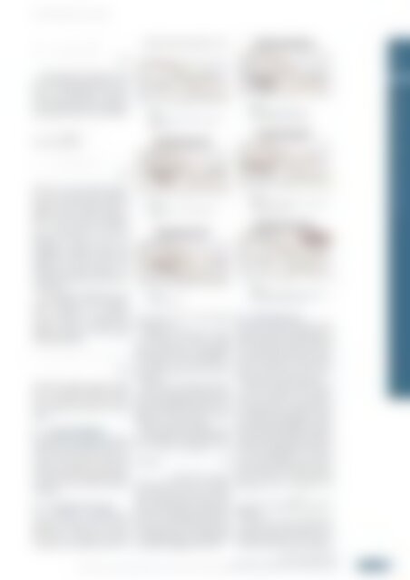
| | Fig. 11.<br />
Diagram of evaluation of failure by plastic<br />
de<strong>for</strong>mation.<br />
| | Fig. 12.<br />
Postulated case circumferential length<br />
of crack.<br />
| | Fig. 13.<br />
Failure Diagram R6.<br />
of the flow of the water flowing<br />
through the core.<br />
Initially, the evaluation was done<br />
in accordance with linear elastic<br />
fracture mechanics. The allowable<br />
crack length is 4.9 inches (Figure 9).<br />
The length of the actual crack is<br />
lower than this limit. So, this crack is<br />
acceptable.<br />
After this, the evaluation was done<br />
under the scope of the Collapse Limit<br />
Load analysis (Figure 10). The allowable<br />
crack length is 16.36 inches. The<br />
length of the actual crack is lower.<br />
There<strong>for</strong>e, it can be accepted.<br />
This evaluation was complemented<br />
with the Failure Assessment Diagram.<br />
The following parameters were<br />
calculated:<br />
and<br />
. As this point is located<br />
within the safe zone. It is considered<br />
safe. However, this point is located<br />
close to the vertical axis in the zone in<br />
which a brittle failure can take place.<br />
So, this is the dominant failure mechanism,<br />
it is recommended to increase<br />
the inspection and to determine the<br />
remaining life because a brittle failure<br />
is undesirable (Figure 11 and 12).<br />
| | Fig. 14.<br />
Failure diagram, postulated case<br />
circumferential projection of crack.<br />
| | Fig. 15.<br />
Failure Assessment Diagram, Postulated case<br />
axial projection of crack.<br />
| | Fig. 16.<br />
Failure Assessment Diagram, Postulated case<br />
circumferential projection of crack.<br />
6.2 Safe helical crack<br />
In this case, a helical crack close to the<br />
weld of the riser brace is postulated. Its<br />
length is 4 inches. Its projections along<br />
the circumferential and the axial axis<br />
are 3.5 inches and 1.94 inches, respectively.<br />
The output power of the reactor<br />
is 100 % and the two circuits of the<br />
RRC system have been in operation.<br />
Initially, the axial projection of the<br />
crack was evaluated. In accordance<br />
with Linear Elastic Fracture Mechanics,<br />
brittle fracture is developed, when<br />
the allowable crack length is greater<br />
than 11.689 inches (Figure 7). Regarding<br />
the ductile failure, the evaluation<br />
was done with the Collapse Limit Load<br />
analysis. The allowable crack length is<br />
11.11 inches (Figure 8). It is greater<br />
than the axial pro jection of the crack.<br />
These results were evaluated with the<br />
Failure Diagram R6. The following<br />
parameters were calculated too.<br />
and ,<br />
then they are localized in the diagram,<br />
Figure 13.<br />
In the case of the circumferential<br />
projection of the helical crack, it was<br />
evaluated against the brittle fracture<br />
with linear elastic fracture mechanics<br />
OPERATION AND NEW BUILD 219<br />
Operation and New Build<br />
Failure Analysis of the Jet Pumps Riser in a Boiling Water Reactor-5<br />
ı Pablo Ruiz-López, Luis Héctor Hernández-Gómez, Juan Cruz-Castro, Gilberto Soto-Mendoza, Juan Alfonso Beltrán-Fernánde and Guillermo Manuel Urriolagoitia-Calderón