St Mary Redcliffe Project 450 RIBA 2 Stage End Report

You also want an ePaper? Increase the reach of your titles
YUMPU automatically turns print PDFs into web optimized ePapers that Google loves.
1563.R1 – <strong>St</strong>age 2 report Page 23 of 29<br />
• The grid method: A grid of copper tape across the surface of the roof. The spacing of the mesh should never be<br />
greater than 20 x 20 metres and on some buildings may have to be less depending on results of the initial risk<br />
assessment.<br />
• Air rods: Rods which protrude above the line of the roof<br />
• Catenary conductors: Conductors suspended above the roof<br />
10.1.12.2 Down Conductors<br />
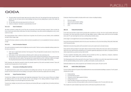
Protection should be provided to all cables which enter or leave a building including:<br />
• Electrical supplies<br />
• Data and communications cabling<br />
• Signal, control and alarm cabling<br />
• CCTV<br />
The down conductors conduct the current from the air terminals to the earth termination network. These can take the<br />
form of earth tape which will be visible down the side of the building or may utilise metallic building fabrics such as steel<br />
columns or rebar.<br />
The spacing between down conductors should never be greater than 20 metres and exact details will be established<br />
during the detail design stage.<br />
The path of the down conductor must be as direct and short as possible and it is not acceptable for the down conductors<br />
to loop.<br />
10.1.12.3 Earth Termination Network<br />
The earth termination network carries the lightning current to earth. There are various acceptable earthing systems but<br />
the most common are:<br />
• Earth rods: A copper-bond rod driven into the ground. They will typically be located around 1 metre from the<br />
edge of the building.<br />
• Earth plates or mats: Used to obtain an effective earth in willow soil with underlying rocks.<br />
• Ring electrode: A ring earth electrode that is sited around the outside of the building can also be used to provide<br />
an earth where the soil is willow. The ring must be in contact with the soil for a minimum of 80% of its length.<br />
The ring should be buried at around 0.5 metres deep and be 1 metre from the edge of the building.<br />
Earth inspection pits should be provided to allow for periodic inspection of the earth termination network. These will<br />
typically have the appearance of small manholes.<br />
10.1.12.4 Connection to Building Main Earth Bar<br />
The lightning protection system will be connected to the building main earth bar. The main earth bar will typically be<br />
found in the main switchroom for the building or at the point at which the electricity supply enters the building.<br />
10.1.12.5 Surge Protection Devices<br />
Transient over voltages are short duration, high magnitude voltage peaks. There are many causes of these over voltages<br />
but lightning strike can be the most extreme and can cause damage to the cabling installation through flashover,<br />
potentially resulting in loss of life through fire and electric shock.<br />
Transient over voltages can also be the cause of data loss and reduced life span or outright failure of sensitive electronic<br />
equipment.<br />
Telecommunication<br />
A site wide communications system will be provided with connections in all areas. The main communication cabinet will<br />
be located in the Vestry back office and will be 42U high, 800mm wide by 1,000mm deep, with front and rear lockable<br />
doors and 19” rack mountings front and rear, and heavy duty lockable castors.<br />
At this stage it is envisaged that the structured cabling will be over CAT6a.<br />
<strong>St</strong>ructured wiring outlet faceplates will be from the same manufacturer as the structured cabling, fitted with CAT6a RJ45<br />
U/UTP shuttered outlets.<br />
Metalclad structured wiring outlets will be provided in areas such as plant rooms and external areas.<br />
Active switches will be provided in each patch cabinet to allow transfer of data to the main server cabinet. All equipment<br />
within the server cabinet will be provided by an ICT specialist appointed separately by the Client in accordance with the<br />
clients requirements e.g. speed, security, data transfer.<br />
All active equipment (Excluding active switches) will be provided by others e.g. telephones, computers, telephone<br />
exchange, server, routers, modems, wifi transmitters, software.<br />
The following data points will be required for this project. These are in addition to any other data requirements associated<br />
with the specified building services systems. E.g. BMS, control panels, security systems, etc.<br />
Dedicated telephone lines will be required for each individual security system, fire alarm and lift.<br />
Audio Video (AV) System<br />
Provision will be made for AV systems to be installed within the new and refurbished buildings as required. The AV system<br />
will generally include:<br />
• Display Lighting<br />
• Sound distribution system<br />
• Temporary control stage equipment stations<br />
• Cabling infrastructure<br />
• Power and Data connections for Flat Screen TV’s and projectors<br />
• Laptop connections will be provided to allow connection of laptops to the TV screen within the room.<br />
The complete AV system detailed requirements will be confirmed and specified by the Client.