

VGB POWERTECH 10 (2020) - International Journal for Generation and Storage of Electricity and Heat
VGB PowerTech - International Journal for Generation and Storage of Electricity and Heat. Issue 7 (2020). Technical Journal of the VGB PowerTech Association. Energy is us! Power plant products/by-products.
VGB PowerTech - International Journal for Generation and Storage of Electricity and Heat. Issue 7 (2020).
Technical Journal of the VGB PowerTech Association. Energy is us!
Power plant products/by-products.

You also want an ePaper? Increase the reach of your titles
YUMPU automatically turns print PDFs into web optimized ePapers that Google loves.
Implementation <strong>of</strong> a slagging prediction tool to lignite blend fired boilers <strong>VGB</strong> PowerTech <strong>10</strong> l <strong>2020</strong><br />
Tab. 1. Ash composition in % <strong>of</strong> the reference coal samples.<br />
Case Ash* S* SiO 2 Al 2 O 3 TiO 2 Fe 2 O 3 CaO MgO K 2 O Na 2 O SO 3 P 2 O 5<br />
1 6.05 0.85 44.00 11.1 0.72 13.1 11.3 2.79 0.77 0.09 14.7 0.11<br />
2 7.86 1.38 49.<strong>10</strong> <strong>10</strong>.3 0.82 11.50 <strong>10</strong>.3 2.35 0.64 0.09 12.5 0.06<br />
3 <strong>10</strong>.<strong>10</strong> 3.45 50.4 14.5 0.84 8.17 <strong>10</strong>.1 2.16 0.88 0.<strong>10</strong> 11.00 0.06<br />
Note: *) percentage in the fuel on as received basis<br />
––<br />
Case 1: date 15.03.2017, low slagging<br />
operation<br />
––<br />
Case 2: date 16.03.2017, medium slagging<br />
operation<br />
––<br />
Case 3: date 21.03.2017, high slagging<br />
operation<br />
The quality <strong>and</strong> ash content <strong>of</strong> lignite blends<br />
fired during the selected cases are compared<br />
in Ta b l e 1 . These blends show a difference<br />
mostly in sulphur <strong>and</strong> ash contents<br />
in the fuel as well as in the Fe 2 O 3 content<br />
in the ash. The highest ash <strong>and</strong> sulphur<br />
amounts were found in the blends <strong>for</strong><br />
case 3 (high slagging) followed by case 2<br />
(medium slagging) <strong>and</strong> then case 1 (low<br />
slagging).<br />
The field slagging observations <strong>for</strong> these<br />
cases differ from the predictions obtained<br />
based on conventional indices. The calculated<br />
conventional slagging index B/A predicted<br />
medium (case 1) or low risk (case 2<br />
<strong>and</strong> 3). Based on the Fe 2 O 3 /CaO index, the<br />
predicted risk was ambiguous. Moreover,<br />
the first two ash fusion temperatures (IDT<br />
<strong>and</strong> ST) determined <strong>for</strong> the three investigated<br />
blends under oxidizing conditions<br />
were on a similar level <strong>of</strong> around 1,190 °C<br />
(please see Ta b l e 2 <strong>and</strong> Ta b l e 3 ). Overall,<br />
the conventional indices could not give<br />
a clear indication about the potential slagging<br />
severity or even showed different slagging<br />
risks as observed during the measurement<br />
campaign. However, based on the<br />
fuel data <strong>and</strong> data collected from the monitoring<br />
tools it was agreed that the ash <strong>and</strong><br />
sulphur contents (mostly associated with<br />
pyrites) as well as reducing conditions inside<br />
the furnace play an important role in<br />
furnace slagging <strong>for</strong> Nochten <strong>and</strong> Reichwalde<br />
lignite blends.<br />
Evaluation <strong>of</strong> the slagging<br />
predictor results<br />
The developed slagging predictor enables<br />
an advanced thermal analysis <strong>of</strong> a boiler<br />
<strong>for</strong> investigating the impact <strong>of</strong> fuel switching<br />
on boiler per<strong>for</strong>mance including the<br />
ash deposition effects. The flue gas temperature<br />
distribution in the furnace, its<br />
maximum value in the most intense heat<br />
release zones as well as at the furnace outlet<br />
mostly determine the slagging conditions<br />
inside the boiler. There are equally<br />
important conditions on the furnace walls,<br />
in terms <strong>of</strong> the wall/deposit outer temperature<br />
<strong>and</strong> the presence <strong>of</strong> reducing atmospheres<br />
along with the furnace height. The<br />
one-dimensional flue gas temperature pr<strong>of</strong>iles<br />
predicted <strong>for</strong> the Unit Q <strong>for</strong> the three<br />
investigated cases (<strong>10</strong>0 % boiler load) <strong>and</strong><br />
Tab. 2. Slagging risk assessment based on conventional indices.<br />
Case B/A* Risk Fe 2 O 3 /CaO** Risk<br />
1 0.503 Medium 1.16 Medium-Severe<br />
2 0.413 Low 1.12 Medium-Severe<br />
3 0.326 Low 0.81 Medium-Severe<br />
Note: *) Base to Acid ratio (B/A), where A = XSiO2 + XAl2O3 + XTiO2, B = XFe2O3 + XCaO + XMgO +<br />
XNa2O + XK2O , <strong>and</strong> Xi is the mass ratio <strong>of</strong> i component in the ash; **) Fe2O3/CaO – Iron-calcium ratio,<br />
where Fe2O3 = XFe2O3, CaO = XCaO , <strong>and</strong> Xi is the mass ratio <strong>of</strong> i component in the ash<br />
Tab. 3. Ash fusion temperatures.<br />
Case 1 2 3<br />
Initial de<strong>for</strong>mation temperature (IDT), o C 1,150 1,160 1,160<br />
S<strong>of</strong>tening temperature (ST), o C 1,200 1,190 1,180<br />
Hemispherical temperature (HT), o C 1,250 1,270 1,320<br />
Flow temperature (FT), o C 1,280 1,430 1,360<br />
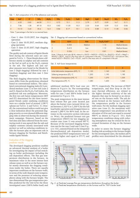
additional medium 80 % load case are<br />
shown in F i g u r e 5a. The corresponding<br />
temperature distribution on the furnace<br />
walls <strong>for</strong> case 3 <strong>and</strong> <strong>10</strong>0 % boiler load is<br />
presented in F i g u r e 5 b .<br />
The peak temperature in the most intense<br />
heat release flue gas zone located just<br />
above the burner rows (around 42 m) varied<br />
between 1,315 o C to 1,330 o C <strong>for</strong> the full<br />
load boiler operation <strong>and</strong> dropped down to<br />
around 1,280 o C <strong>for</strong> 80 % load. In the entrance<br />
to the convective section (elevation<br />
ca. 94 m), the predicted furnace exit gas<br />
temperature (FEGT) <strong>for</strong> low slagging operation<br />
case (case 1) was around 967 o C.<br />
Because <strong>of</strong> the increased slagging <strong>for</strong>mation<br />
rate <strong>for</strong> the case 2 <strong>and</strong> case 3 (see F i g -<br />
u r e 6 b ), assessed based on the integrated<br />
thermochemical ash deposition model,<br />
the predicted FEGT temperatures were adequately<br />
higher <strong>and</strong> equal to 971 o C <strong>and</strong><br />
a) b)<br />
991 o C, respectively. The increase <strong>of</strong> FEGT<br />
temperature, <strong>and</strong> thus drop in the furnace<br />
thermal efficiency, are related to<br />
the higher thermal resistivity <strong>of</strong> the ash<br />
deposits that may be <strong>for</strong>med at an elevated<br />
rate on the furnace walls. The ash deposits<br />
<strong>for</strong>med on the furnace wall affect<br />
the temperature pr<strong>of</strong>ile in the furnace<br />
wall zones. For the medium slagging operation<br />
case (case 2), the maximum wall/<br />
deposit temperature was predicted at the<br />
elevation <strong>of</strong> 42 m <strong>and</strong> was equal to around<br />
900 o C as shown in F i g u r e 5 b ). Such<br />
temperature conditions along with reducing<br />
atmospheres may be critical <strong>for</strong> the increased<br />
<strong>for</strong>mation <strong>of</strong> slag on the furnace<br />
walls.<br />
In order to assess the furnace slagging/<br />
fouling risk according to the furnace height<br />
<strong>for</strong> the investigated cases, the molten ash %<br />
pr<strong>of</strong>iles were determined <strong>for</strong> the obtained<br />
Fig. 5. a) Predicted average flue gas temperature distributions throughout the boiler;<br />
b) Predicted temperature distribution on the furnace wall <strong>for</strong> <strong>10</strong>0 % boiler load.<br />
60


