analise dinâmica de um chiller de absorção de brometo de lítio ...
analise dinâmica de um chiller de absorção de brometo de lítio ...
analise dinâmica de um chiller de absorção de brometo de lítio ...
- No tags were found...

You also want an ePaper? Increase the reach of your titles
YUMPU automatically turns print PDFs into web optimized ePapers that Google loves.
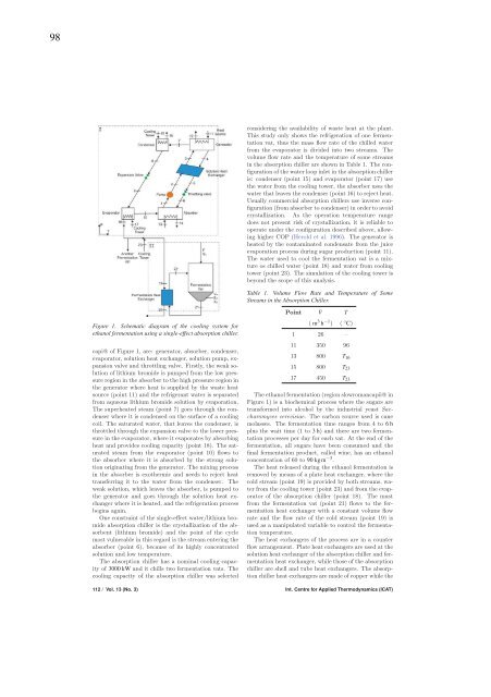
98Figure 1. Schematic diagram of the cooling system forethanol fermentation using a single-effect absorption <strong>chiller</strong>.capi@ of Figure 1, are: generator, absorber, con<strong>de</strong>nser,evaporator, solution heat exchanger, solution p<strong>um</strong>p, expansionvalve and throttling valve. Firstly, the weak solutionof lithi<strong>um</strong> bromi<strong>de</strong> is p<strong>um</strong>ped from the low pressureregion in the absorber to the high pressure region inthe generator where heat is supplied by the waste heatsource (point 11) and the refrigerant water is separatedfrom aqueous lithi<strong>um</strong> bromi<strong>de</strong> solution by evaporation.The superheated steam (point 7) goes through the con<strong>de</strong>nserwhere it is con<strong>de</strong>nsed on the surface of a coolingcoil. The saturated water, that leaves the con<strong>de</strong>nser, isthrottled through the expansion valve to the lower pressurein the evaporator, where it evaporates by absorbingheat and provi<strong>de</strong>s cooling capacity (point 18). The saturatedsteam from the evaporator (point 10) flows tothe absorber where it is absorbed by the strong solutionoriginating from the generator. The mixing processintheabsorberisexothermicandneedstorejectheattransferring it to the water from the con<strong>de</strong>nser. Theweak solution, which leaves the absorber, is p<strong>um</strong>ped tothe generator and goes through the solution heat exchangerwhere it is heated, and the refrigeration processbegins again.One constraint of the single-effect water/lithi<strong>um</strong> bromi<strong>de</strong>absorption <strong>chiller</strong> is the crystallization of the absorbent(lithi<strong>um</strong> bromi<strong>de</strong>) and the point of the cyclemost vulnerable in this regard is the stream entering theabsorber (point 6), because of its highly concentratedsolution and low temperature.The absorption <strong>chiller</strong> has a nominal cooling capacityof 3000 kW and it chills two fermentation vats. Thecooling capacity of the absorption <strong>chiller</strong> was selectedconsi<strong>de</strong>ring the availability of waste heat at the plant.This study only shows the refrigeration of one fermentationvat, thus the mass flow rate of the chilled waterfrom the evaporator is divi<strong>de</strong>d into two streams. Thevol<strong>um</strong>e flow rate and the temperature of some streamsin the absorption <strong>chiller</strong> are shown in Table 1. The configurationof the water loop inlet in the absorption <strong>chiller</strong>is: con<strong>de</strong>nser (point 15) and evaporator (point 17) usethe water from the cooling tower, the absorber uses thewater that leaves the con<strong>de</strong>nser (point 16) to reject heat.Usually commercial absorption <strong>chiller</strong>s use inverse configuration(from absorber to con<strong>de</strong>nser) in or<strong>de</strong>r to avoidcrystallization. As the operation temperature rangedoes not present risk of crystallization, it is reliable tooperate un<strong>de</strong>r the configuration <strong>de</strong>scribed above, allowinghigher COP (Herold et al. 1996). The generator isheated by the contaminated con<strong>de</strong>nsate from the juiceevaporation process during sugar production (point 11).The water used to cool the fermentation vat is a mixtureos chilled water (point 18) and water from coolingtower (point 23). The simulation of the cooling tower isbeyond the scope of this analysis.Table 1. Vol<strong>um</strong>e Flow Rate and Temperature of SomeStreams in the Absorption Chiller.Point ˙V T( m 3 h −1 ) ( ◦ C)1 26 –11 350 9613 800 T 1615 800 T 2317 450 T 23The ethanol fermentation (region slowromancapii@ inFigure 1) is a biochemical process where the sugars aretransformed into alcohol by the industrial yeast Saccharomycescerevisiae. The carbon source used is canemolasses. The fermentation time ranges from 4 to 6hplus the wait time (1 to 3h) and there are two fermentationprocesses per day for each vat. At the end of thefermentation, all sugars have been cons<strong>um</strong>ed and thefinal fermentation product, called wine, has an ethanolconcentration of 60 to 90 kg m −3 .The heat released during the ethanol fermentation isremoved by means of a plate heat exchanger, where thecold stream (point 19) is provi<strong>de</strong>d by both streams, waterfrom the cooling tower (point 23) and from the evaporatorof the absorption <strong>chiller</strong> (point 18). The mustfrom the fermentation vat (point 21) flows to the fermentationheat exchanger with a constant vol<strong>um</strong>e flowrate and the flow rate of the cold stream (point 19) isused as a manipulated variable to control the fermentationtemperature.The heat exchangers of the process are in a counterflow arrangement. Plate heat exchangers are used at thesolution heat exchanger of the absorption <strong>chiller</strong> and fermentationheat exchanger, while those of the absorption<strong>chiller</strong> are shell and tube heat exchangers. The absorption<strong>chiller</strong> heat exchangers are ma<strong>de</strong> of copper while the112 / Vol. 13 (No. 3) Int. Centre for Applied Thermodynamics (ICAT)