
Erfolgreiche ePaper selbst erstellen
Machen Sie aus Ihren PDF Publikationen ein blätterbares Flipbook mit unserer einzigartigen Google optimierten e-Paper Software.
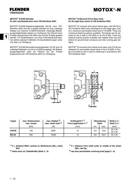
<strong>MOTOX</strong> ® -N-EHB Getriebe<br />
für den Leichtlastbereich nach VDI-Richtlinie 3643<br />
<strong>MOTOX</strong> ® -N-EHB-Kegelstirnradgetriebe BH.38 nach VDI-<br />
Richtlinie 3643 sind als 2-stufige Getriebe für eine zulässige<br />
Radlast von maximal 10.000N entwickelt. Vielseitige Befestigungsmöglichkeiten<br />
stehen zur Verfügung. Der Flansch kann<br />
A-seitig entsprechend VDI 3643 oder auf der B-Seite gewählt<br />
werden. Für Bodenförderer und neue Fahrwerkskonstruktionen<br />
stehen optional Fußleisten mit Gewindebohrungen unten<br />
und oben zur Verfügung.<br />
<strong>MOTOX</strong> ® -N-EHB-Stirnradschneckengetriebe CH.28 sind für<br />
zulässige Radlasten von bis zu 6.500N ausgelegt. Als Befestigungsmöglichkeit<br />
steht ein Flansch auf der A-Seite<br />
entsprechend der VDI-Richtlinie 3643 zur Verfügung.<br />
#<br />
Typ(e) max. Drehmoment<br />
max. torque<br />
1 - 16<br />
max. Radlast 2)<br />
max. wheel load 2)<br />
<strong>MOTOX</strong> ® -N<br />
<strong>MOTOX</strong> ® -N-Monorail Drive Gear Units<br />
for the light-duty sector to VDI Guideline 3643<br />
<strong>MOTOX</strong> ® -N monorail drive bevel helical gear units BH.38 to<br />
VDI Guideline 3643 were developed as two-stage gear units<br />
for a maximum permissible wheel load of 10,000N. There are<br />
numerous fastening options available. The flange can be selected<br />
on the A side to VDI 3643 or on the B side. There are<br />
optional bearing boards available with tapped holes top and<br />
bottom for ground-level conveyors and new running gear designs.<br />
<strong>MOTOX</strong> ® -N monorail drive helical worm gear units CH.28 are<br />
designed for permissible wheel loads of up to 6,500N. A flange<br />
is provided on the A side for fastening in accordance with<br />
VDI Guideline 3643.<br />
Kraftangriff X 1)<br />
Force application X 1)<br />
Übersetzung<br />
Ratio<br />
Welle d x l<br />
Shaft d x l<br />
[Nm] [N] [mm] min. max. [mm]<br />
CHF28 100 6500 13 8,2 73,9<br />
20 x 35<br />
25 x 35<br />
BH.38 200 10000 13 8,6 63,9 25 x 35<br />
1)<br />
X = Abstand Mitte Laufrad zu Wellenbund (ML), siehe<br />
Bild<br />
2)<br />
siehe auch zul. Radialkräfte (Seite 2 - 6)<br />
1)<br />
X = distance from shaft collar to middle of the wheel<br />
(ML), see fig.<br />
2)<br />
see also permissible overhung load (page 2 - 6)