Pre-Phase A Report - Lisa - Nasa
Pre-Phase A Report - Lisa - Nasa
Pre-Phase A Report - Lisa - Nasa
Create successful ePaper yourself
Turn your PDF publications into a flip-book with our unique Google optimized e-Paper software.
4.2 Noises and error sources 93<br />
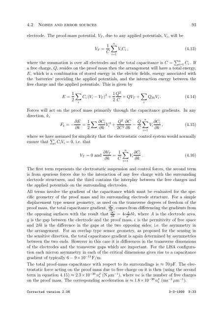
electrode. The proof-mass potential, VT , due to any applied potentials, Vi, will be<br />
VT = 1<br />
C<br />
n<br />
ViCi , (4.13)<br />
i=1<br />
where the summation is over all electrodes and the total capacitance is C = n<br />
i=1 Ci .If<br />
a free charge, Q, resides on the proof mass then the arrangement will have a total energy,<br />
E, which is a combination of stored energy in the electric fields, energy associated with<br />
the ‘batteries’ providing the applied potentials, and the interaction energy between the<br />
free charge and the applied potentials. This is given by<br />
E = 1<br />
2<br />
<br />
i<br />
Ci (Vi − VT ) 2 + 1 Q<br />
2<br />
2<br />
C + QVT + <br />
QBiVi . (4.14)<br />
Forces will act on the proof mass primarily through the capacitance gradients. In any<br />
direction, k,<br />
Fk = − ∂E 1 ∂Ci 2<br />
= Vi +<br />
∂k 2 ∂k Q2<br />
2C2 n<br />
∂C Q ∂Ci<br />
− Vi , (4.15)<br />
∂k C ∂k<br />
where we have assumed for simplicity that the electrostatic control system would normally<br />
ensure that <br />
i CiVi = 0, i.e. that<br />
VT =0and ∂VT<br />
∂k<br />
= 1<br />
C<br />
n<br />
i=1<br />
i<br />
i=1<br />
∂Ci<br />
Vi . (4.16)<br />
∂k<br />
The first term represents the electrostatic suspension and control forces, the second term<br />
is from spurious forces due to the interaction of any free charge with the surrounding<br />
electrode structures, and the third contains the interplay between the free charges and<br />
the applied potentials on the surrounding electrodes.<br />
All terms involve the gradient of the capacitance which must be evaluated for the specific<br />
geometry of the proof mass and its surrounding electrode structure. For a simple<br />
displacement type sensor geometry, as used on the transverse degrees of freedom of the<br />
proof mass, the total capacitance gradient, ∂C,<br />
comes from differencing the gradients from<br />
∂k<br />
the opposing surfaces with the result that ∂C A<br />
=4ɛ ∂k g3 δk, whereAis the electrode area,<br />
g is the gap between the electrode and the proof mass, ɛ is the permitivity of free space<br />
and 2δk is the difference in the gaps at the two opposing sides; i.e. the asymmetry in<br />
the arrangement. For an overlap type sensor geometry, as proposed for the sensing in<br />
the sensitive direction, the total capacitance gradient is again determined by asymmetries<br />
between the two ends. However in this case it is differences in the transverse dimensions<br />
of the electrodes and the transverse gaps which are important. For the LISA configuration<br />
each micron asymmetry in each of the critical dimensions gives rise to a capacitance<br />
gradient of typically 6 − 9×10⁻¹³ F/m.<br />
The total proof-mass capacitance with respect to its surroundings is ≈ 70 pF. The electrostatic<br />
force acting on the proof mass due to free charge on it is then (using the second<br />
term in equation 4.15) ≈ 2.3×10⁻³⁰ n2 e (N µm−1 ), where ne is the number of free charges<br />
on the proof mass. The corresponding acceleration is ≈ 1.8×10⁻³⁰ n2 e (ms−2 µm−1 ).<br />
Corrected version 2.08 3-3-1999 9:33


