

Pre-Phase A Report - Lisa - Nasa
Pre-Phase A Report - Lisa - Nasa
Pre-Phase A Report - Lisa - Nasa

Create successful ePaper yourself
Turn your PDF publications into a flip-book with our unique Google optimized e-Paper software.
7.3 Micronewton ion thrusters 153<br />
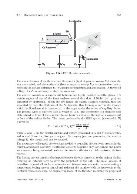
Figure 7.5 FEEP thruster schematic.<br />
The main elements of the thruster are the emitter (kept at positive voltage Ve) where the<br />
ions are created, and the accelerator (kept at negative voltage Va), a counter-electrode to<br />
establish the voltage difference Ve −Va needed for ionization and acceleration. A threshold<br />
voltage of 7 kV is necessary to start the emission.<br />
The emitter consists of a narrow slit between two highly polished metallic plates. On<br />
certain regions of one of the inner surfaces several thin dots of Nickel (≈ 1 µm) are<br />
deposited by sputtering. When the two halves are tightly clamped together, they are<br />
separated by only the thickness of the Ni deposits, thus forming a narrow slit through<br />
which the liquid metal is transported to the edges under the action of capillary forces.<br />
The present types of emitters have a weight of 15 g. The accelerator is a stainless steel<br />
plate placed in front of the emitter; the ion beam is extracted through an elongated slit<br />
in front of the emitter blades. The thrust produced by the FEEP system (measured in N)<br />
is given by<br />
F =1.66×10 −3 I e V 1/2<br />
e<br />
sin α<br />
α<br />
sin β<br />
β<br />
, (7.1)<br />
where Ie and Ve are the emitter current and voltage (measured in A and V, respectively),<br />
and α and β are the divergence angles. By varying just one parameter, the emitter<br />
voltage Ve, the thrust level can be changed.<br />
The neutralizer will supply the electrons needed to neutralize the ion beam created in the<br />
emitter/accelerator assembly. Neutralizer concepts requiring only low current and power<br />
are currently being evaluated, such as thermionic cathodes and field emission electron<br />
sources.<br />
The feeding system consists of a shaped reservoir directly connected to the emitter blades,<br />
requiring no external force to drive the propellant to the slit. The small amount of<br />
propellant required allows for a self-contained, integral reservoir unit, thus eliminating a<br />
complicated feeding system control and reducing the interface with the spacecraft to the<br />
electrical connections only. An engineering model of the thruster, including the propellant<br />
Corrected version 2.08 3-3-1999 9:33