

Pre-Phase A Report - Lisa - Nasa
Pre-Phase A Report - Lisa - Nasa
Pre-Phase A Report - Lisa - Nasa

Create successful ePaper yourself
Turn your PDF publications into a flip-book with our unique Google optimized e-Paper software.
3.1 The interferometer 57<br />
3.1.4 System requirements<br />
Laser power and shot noise. To attain the desired gravitational wave sensitivity<br />
the system must keep the noise in measuring the differences in round trip path length<br />
between two arms below 40×10 −12 m/ √ Hz , over a frequency range from 10 −3 to 10 −1 Hz.<br />
A number of noise sources limit the performance, as will be seen in the noise budget<br />
given in Section 4.2 . However the fundamental, and most significant, noise source will<br />
be due to photoelectron shot noise in the detected photocurrents. Consideration of the<br />
noise budget suggests that the limitation due to photoelectron shot noise in each detector<br />
should not exceed about 10×10 −12 m/ √ Hz . The amount of light used in the measurment<br />
depends both on the laser power and the efficiency of the transmission of light from the<br />
emitting laser to the detection diode on the far spacecraft. This efficiency is limited by<br />
the divergence of the laser beam as it is transmitted over the 5×10 6 km arm and losses<br />
in the various components in the optical chain.<br />
Beam divergence. Even the best collimated laser beam will still have some finite<br />
divergence governed by the size of the final optic. With a Gaussian beam optimised for<br />
transmission between mirrors of diameter D, withanarmlengthL, and a transmitted<br />
power P , the power received at the far craft is given by<br />
Pr =0.50 D4<br />
λ2 P. (3.1)<br />
L2 This is the case when the Gaussian beam has a waist (of radius w) at the transmitting<br />
craft that almost fills the final telescope mirror, w =0.446 D.<br />
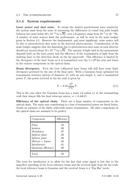
Efficiency of the optical chain. There are a large number of components in the<br />
optical chain. The main ones contributing to a loss of transmitted power are listed below,<br />
beside an estimate of the likely achievable power transmission. All other components in<br />
the optical chain are assumed to be perfect.<br />
Component Efficiency<br />
Fibre .70<br />
Isolator .96<br />
Modulator .97<br />
Splitter plate .90<br />
Splitter plate .90<br />
Mirrors + lenses .88<br />
Interference .81<br />
Quantum efficiency .80<br />
Total .30<br />
The term for interference is to allow for the fact that some signal is lost due to the<br />
imperfect matching of the local reference beam and the received light from the far craft:<br />
the local reference beam is Gaussian and the received beam is a ‘Top Hat’ mode.<br />
Corrected version 2.08 3-3-1999 9:33