

Pre-Phase A Report - Lisa - Nasa
Pre-Phase A Report - Lisa - Nasa
Pre-Phase A Report - Lisa - Nasa

You also want an ePaper? Increase the reach of your titles
YUMPU automatically turns print PDFs into web optimized ePapers that Google loves.
60 Chapter 3 Experiment Description<br />
Diodes<br />
Diode heaters<br />
Crystal heater<br />
Crystal<br />
Fiber coupler<br />
LIGHT<br />
Laserhead Supply Unit EOM Photodiode<br />
Diode current<br />
source<br />
Diode temperature<br />
controller<br />
Crystal temperature<br />
controller<br />
Frequency stab.<br />
feedback servo<br />
Power stab.<br />
feedback servo<br />
POWER RS 422<br />
Spacecraft BUS<br />
10 MHz<br />
LiNbO<br />
crystal<br />
Optics Bench<br />
InGaAs<br />
diode<br />
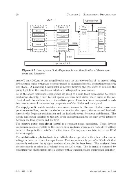
Figure 3.5 Laser system block diagramm for the identification of the components<br />
and interfaces.<br />
area of 1 µm×200 µm at unit magnification onto the entrance surface of the crystal, using<br />
two identical lenses with plano-convex surfaces to minimize spherical aberration (best form<br />
lens shape). A polarizing beamsplitter is inserted between the two lenses to combine the<br />
pump light from the two diodes, which are orthogonal in polarization.<br />
All of the above mentioned components are glued to a solid fused silica spacer to ensure<br />
mechanical stability. Glued to that spacer are three heat sinks, which serve as the mechanical<br />
and thermal interface to the radiator plate. There is a heater integrated in each<br />
heat sink to control the operating temperature of the diodes and the crystal.<br />
The supply unit mainly contains two current sources for the laser diodes, three temperature<br />
controllers, two for the diodes and one for the crystal, the mixer and feedback<br />
servo for the frequency stabilisation and the feedback circuit for power stabilisation. The<br />
supply unit power interface to the S/C power subsystem shall be the only power interface<br />
between the laser system and the S/C.<br />
The electro-optic modulator (EOM) is a resonant phase modulator. These devices<br />
use lithium niobate crystals as the electro-optic medium, where a few volts drive voltage<br />
induce a change in the crystal‘s refractive index. The only electrical interface to the EOM<br />
is the rf supply.<br />
The stabilisation photodiode is a InGaAs diode operated with a few volts reverse<br />
voltage in order to reduce its capacitance. That capacitance is part of a LC-circuit that<br />
resonantly enhances the rf signal modulated on the the laser beam. The ac-signal from<br />
the photodiode is taken as a voltage from the LC-circuit. The dc-signal is obtained by<br />
converting the photocurrent into a voltage with a transimpedance operational amplifier.<br />
3-3-1999 9:33 Corrected version 2.08<br />
AC<br />
pathl<br />
DC<br />
pathl