

Pre-Phase A Report - Lisa - Nasa
Pre-Phase A Report - Lisa - Nasa
Pre-Phase A Report - Lisa - Nasa

Create successful ePaper yourself
Turn your PDF publications into a flip-book with our unique Google optimized e-Paper software.
3.2 The inertial sensor 69<br />
and the level of the disturbing effects resulting from the presence of the instrument cage<br />
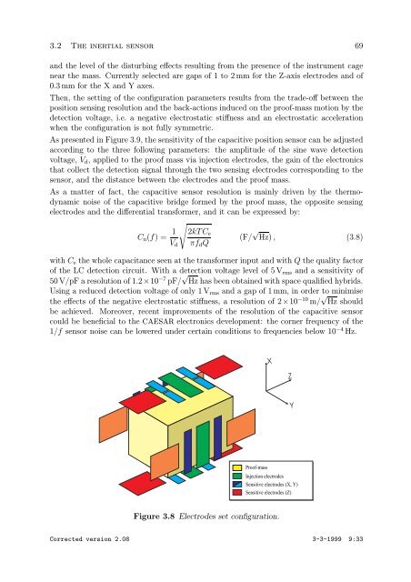
near the mass. Currently selected are gaps of 1 to 2 mm for the Z-axis electrodes and of<br />
0.3 mm for the X and Y axes.<br />
Then, the setting of the configuration parameters results from the trade-off between the<br />
position sensing resolution and the back-actions induced on the proof-mass motion by the<br />
detection voltage, i.e. a negative electrostatic stiffness and an electrostatic acceleration<br />
when the configuration is not fully symmetric.<br />
As presented in Figure 3.9, the sensitivity of the capacitive position sensor can be adjusted<br />
according to the three following parameters: the amplitude of the sine wave detection<br />
voltage, Vd, applied to the proof mass via injection electrodes, the gain of the electronics<br />
that collect the detection signal through the two sensing electrodes corresponding to the<br />
sensor, and the distance between the electrodes and the proof mass.<br />
As a matter of fact, the capacitive sensor resolution is mainly driven by the thermodynamic<br />
noise of the capacitive bridge formed by the proof mass, the opposite sensing<br />
electrodes and the differential transformer, and it can be expressed by:<br />
<br />
Cn(f) = 1<br />
Vd<br />
2kTCe<br />
πfdQ<br />
(F/ √ Hz) , (3.8)<br />
with Ce the whole capacitance seen at the transformer input and with Q the quality factor<br />
of the LC detection circuit. With a detection voltage level of 5 Vrms and a sensitivity of<br />
50 V/pF a resolution of 1.2×10 −7 pF/ √ Hz has been obtained with space qualified hybrids.<br />
Using a reduced detection voltage of only 1 Vrms and a gap of 1 mm, in order to minimise<br />
the effects of the negative electrostatic stiffness, a resolution of 2×10 −10 m/ √ Hz should<br />
be achieved. Moreover, recent improvements of the resolution of the capacitive sensor<br />
could be beneficial to the CAESAR electronics development: the corner frequency of the<br />
1/f sensor noise can be lowered under certain conditions to frequencies below 10 −4 Hz.<br />
Figure 3.8 Electrodes set configuration.<br />
Corrected version 2.08 3-3-1999 9:33