

Pre-Phase A Report - Lisa - Nasa
Pre-Phase A Report - Lisa - Nasa
Pre-Phase A Report - Lisa - Nasa

Create successful ePaper yourself
Turn your PDF publications into a flip-book with our unique Google optimized e-Paper software.
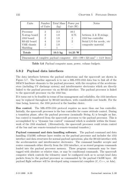
132 Chapter 5 Payload Design<br />
Units Number Total Mass Power per Notes<br />
of Units (kg) Unit (W)<br />
Processor 2 2.3 10.5<br />
X-strap board 2 1.8 0.75 between A & B strings<br />
1553 board 2 1.8 1 1553 bus controller<br />
RS 422 board 4 1.8 2 Serial I/O for accels., etc<br />
VME chassis 2 1.8 – composite material<br />
Shielding – 1 –<br />
Totals 10.5 kg 14.25 W<br />
Dimensions of complete payload computer: 233×199×321 mm 3 =14.9 litres<br />
Table 5.6 Payload computer mass, power, volume budgets.<br />
5.9.2 Payload data interfaces<br />
The data interfaces between the payload subsystems and the spacecraft are shown in<br />
Figure 5.7 . The baseline approach is to use a MIL-STD-1553 data bus to link all of the<br />
DFACS hardware elements to the payload processor, with the exception of the accelerometers<br />
(including UV discharge system) and interferometer electronics which are directly<br />
linked to the payload processor via an RS 422 interface. The payload processor is linked<br />
to the spacecraft processor via the 1553 bus.<br />
If it turns out to be feasible in terms of bus management and reliability, the 1553 interfaces<br />
may be replaced throughout by RS 422 interfaces, with considerable cost benefit. For the<br />
time being, however, the 1553 protocol is the baseline choice.<br />
Bus control. The MIL-STD-1553 protocol requires no more than one bus controller.<br />
Initially, the spacecraft processor is the bus controller for coarse attitude control. During<br />
a transition phase, after the payload processor (nominally String A) is brought on line,<br />
bus control is transferred from the spacecraft processor to the payload processor. This is<br />
accomplished by a “dynamic bus control” command which is available within the framework<br />
of the 1553 standard. (Alternatively, the spacecraft processor could retain control<br />
of the bus and use remote-terminal-to-remote-terminal transfers.)<br />
Payload command and data handling software. The payload command and data<br />
handling (C&DH) software layer resides on the payload processor and includes the 1553<br />
interface and data structures for normal payload operations, plus the RS 422 interface with<br />
the accelerometers and interferometer electronics. The command handler accepts and<br />
routes commands either directly from the 1553 interface, or as stored program commands<br />
loaded into the payload processor memory. These program commands may be timetagged<br />
with absolute or relative time, or may be conditional commands. The spacecraft<br />
computer which controls the telemetry must be configured such as to accept/send data<br />
packets from/to the payload processor as commanded by the payload C&DH layer. All<br />
payload flight software will be developed using commercial compilers (C, C++, orAda).<br />
3-3-1999 9:33 Corrected version 2.08