

Pre-Phase A Report - Lisa - Nasa
Pre-Phase A Report - Lisa - Nasa
Pre-Phase A Report - Lisa - Nasa

You also want an ePaper? Increase the reach of your titles
YUMPU automatically turns print PDFs into web optimized ePapers that Google loves.
128 Chapter 5 Payload Design<br />
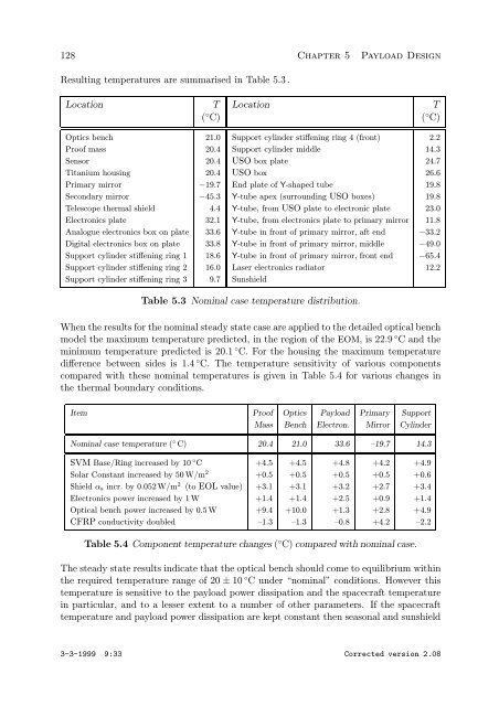
Resulting temperatures are summarised in Table 5.3 .<br />
Location T Location T<br />
( ◦ C) ( ◦ C)<br />
Optics bench 21.0 Support cylinder stiffening ring 4 (front) 2.2<br />
Proof mass 20.4 Support cylinder middle 14.3<br />
Sensor 20.4 USO box plate 24.7<br />
Titanium housing 20.4 USO box 26.6<br />
Primary mirror −19.7 End plate of Y-shaped tube 19.8<br />
Secondary mirror −45.3 Y-tube apex (surrounding USO boxes) 19.8<br />
Telescope thermal shield 4.4 Y-tube, from USO plate to electronic plate 23.0<br />
Electronics plate 32.1 Y-tube, from electronics plate to primary mirror 11.8<br />
Analogue electronics box on plate 33.6 Y-tube in front of primary mirror, aft end −33.2<br />
Digital electronics box on plate 33.8 Y-tube in front of primary mirror, middle −49.0<br />
Support cylinder stiffening ring 1 18.6 Y-tube in front of primary mirror, front end −65.4<br />
Support cylinder stiffening ring 2 16.0 Laser electronics radiator 12.2<br />
Support cylinder stiffening ring 3 9.7 Sunshield<br />
Table 5.3 Nominal case temperature distribution.<br />
When the results for the nominal steady state case are applied to the detailed optical bench<br />
model the maximum temperature predicted, in the region of the EOM, is 22.9 ◦ Candthe<br />
minimum temperature predicted is 20.1 ◦ C. For the housing the maximum temperature<br />
difference between sides is 1.4 ◦ C. The temperature sensitivity of various components<br />
compared with these nominal temperatures is given in Table 5.4 for various changes in<br />
the thermal boundary conditions.<br />
Item Proof Optics Payload Primary Support<br />
Mass Bench Electron. Mirror Cylinder<br />
Nominal case temperature ( ◦ C) 20.4 21.0 33.6 –19.7 14.3<br />
SVM Base/Ring increased by 10 ◦ C +4.5 +4.5 +4.8 +4.2 +4.9<br />
Solar Constant increased by 50 W/m 2 +0.5 +0.5 +0.5 +0.5 +0.6<br />
Shield αs incr. by 0.052 W/m 2 (to EOL value) +3.1 +3.1 +3.2 +2.7 +3.4<br />
Electronics power increased by 1 W +1.4 +1.4 +2.5 +0.9 +1.4<br />
Optical bench power increased by 0.5 W +9.4 +10.0 +1.3 +2.8 +4.9<br />
CFRP conductivity doubled –1.3 –1.3 –0.8 +4.2 –2.2<br />
Table 5.4 Component temperature changes ( ◦ C) compared with nominal case.<br />
The steady state results indicate that the optical bench should come to equilibrium within<br />
the required temperature range of 20 ± 10 ◦ C under “nominal” conditions. However this<br />
temperature is sensitive to the payload power dissipation and the spacecraft temperature<br />
in particular, and to a lesser extent to a number of other parameters. If the spacecraft<br />
temperature and payload power dissipation are kept constant then seasonal and sunshield<br />
3-3-1999 9:33 Corrected version 2.08