

Pre-Phase A Report - Lisa - Nasa
Pre-Phase A Report - Lisa - Nasa
Pre-Phase A Report - Lisa - Nasa

Create successful ePaper yourself
Turn your PDF publications into a flip-book with our unique Google optimized e-Paper software.
4.2 Noises and error sources 95<br />
is not significant. A charge limit is then derived by requiring that these spring constant<br />
terms do not upset the nominal spring constant from the electrostatic control system by<br />
more than 10 %.<br />
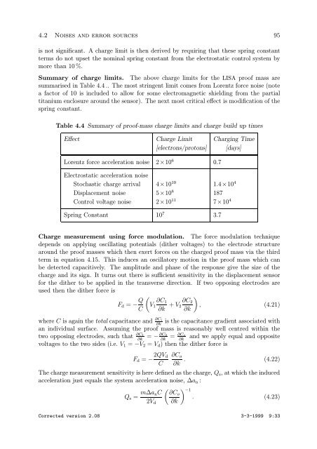
Summary of charge limits. The above charge limits for the LISA proof mass are<br />
summarised in Table 4.4 .. The most stringent limit comes from Lorentz force noise (note<br />
a factor of 10 is included to allow for some electromagnetic shielding from the partial<br />
titanium enclosure around the sensor). The next most critical effect is modification of the<br />
spring constant.<br />
Table 4.4 Summary of proof-mass charge limits and charge build up times<br />
Effect Charge Limit Charging Time<br />
[electrons/protons] [days]<br />
Lorentz force acceleration noise 2×10 6 0.7<br />
Electrostatic acceleration noise<br />
Stochastic charge arrival 4×10 10 1.4×10 4<br />
Displacement noise 5×10 8 187<br />
Control voltage noise 2×10 11 7×10 4<br />
Spring Constant 10 7 3.7<br />
Charge measurement using force modulation. The force modulation technique<br />
depends on applying oscillating potentials (dither voltages) to the electrode structure<br />
around the proof masses which then exert forces on the charged proof mass via the third<br />
term in equation 4.15. This induces an oscillatory motion in the proof mass which can<br />
be detected capacitively. The amplitude and phase of the response give the size of the<br />
charge and its sign. It turns out there is sufficient sensitivity in the displacement sensor<br />
for the dither to be applied in the transverse direction. If two opposing electrodes are<br />
used then the dither force is<br />
Fd = − Q<br />
<br />
<br />
∂C1 ∂C2<br />
V1 + V2 , (4.21)<br />
C ∂k ∂k<br />
where C is again the total capacitance and ∂Ci is the capacitance gradient associated with<br />
∂k<br />
an individual surface. Assuming the proof mass is reasonably well centred within the<br />
two opposing electrodes, such that ∂C1 ∂C2 ∂Co<br />
= − = and we apply equal and opposite<br />
∂k ∂k ∂k<br />
voltages to the two sides (i.e. V1 = −V2 = Vd) then the dither force is<br />
Fd = − 2QVd<br />
C<br />
∂Co<br />
∂k<br />
. (4.22)<br />
The charge measurement sensitivity is here defined as the charge, Qs, at which the induced<br />
acceleration just equals the system acceleration noise, ∆an :<br />
Qs = m∆anC<br />
−1 ∂Co<br />
. (4.23)<br />
2Vd ∂k<br />
Corrected version 2.08 3-3-1999 9:33