Pre-Phase A Report - Lisa - Nasa
Pre-Phase A Report - Lisa - Nasa
Pre-Phase A Report - Lisa - Nasa
You also want an ePaper? Increase the reach of your titles
YUMPU automatically turns print PDFs into web optimized ePapers that Google loves.
4.4 Data analysis 111<br />
with the phase modulation Φ(t) as given in Eq. (4.69) and the modulated amplitude<br />
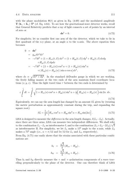
T (h+ + h×) T t (cf. Eq. 4.64). To see how the gravitational-wave detector works, recall<br />
that General Relativity predicts that a ray of light connects a set of points by an interval<br />
of zero or<br />
ds 2 =0. (4.72)<br />
For simplicity, let us consider first one arm of the the detector, which we take to lie in<br />
first quadrant of the x-y plane, at an angle α to the x-axis. The above equation then<br />
becomes<br />
0 = ds 2<br />
= gµνdx µ dx ν<br />
= −c 2 dt 2 +(1+Hxx(t, x)) dx 2 +(1+Hyy(t, x)) dy 2 + Hxy(t, x) dxdy<br />
+Hyx(t, x) dydx<br />
= −c 2 dt 2 +[(1+Hxx(s)) cos 2 α +(1+Hyy(s)) sin 2 α<br />
+( Hxy(s)+Hyx(s))sinαcos α] ds 2 , (4.73)<br />
where ds ≡ dx 2 + dy 2 . In the standard deDonder gauge in which we are working,<br />
the freely falling masses at the two ends of the arm maintain fixed coordinate locations<br />
(x, y, z). Thus the light travel time τ between the two ends is determined by<br />
<br />
c<br />
0<br />
τ<br />
dt =<br />
L<br />
0<br />
<br />
1+Hxx(s)cos 2 α + Hyy(s)sin 2 α + 1<br />
2<br />
<br />
<br />
Hxy(s)+Hyx(s) sin 2α ds.<br />
(4.74)<br />
Equivalently, we can say the arm length has changed by an amount δL given by (treating<br />
the metric perturbation as approximately constant during the trip, and expanding the<br />
square root):<br />
δL = 1<br />
2 L<br />
<br />
Hxx cos 2 α + Hyy sin 2 <br />
α + Hxy sin(2α) . (4.75)<br />
LISA is designed to measure the difference in the arm length changes, δ(L1−L2). Actually,<br />
since there are three arms, LISA can measure two independent differences. We shall refer<br />
to the combination L1−L2 as interferometer I, and to the combination (L1+L2−2L3)/ √ 3<br />
as interferometer II. For simplicity, we let L1 make a 15 0 angle to the x-axis, while L2<br />
makes a 75 0 angle (i.e., α = π/12 and 5π/12 for L1 and L2, respectively).<br />
From Eq. (4.75) one easily shows that the strains associated with these particular combinations<br />
are<br />
√<br />
3<br />
hI =<br />
4 (Hxx − Hyy) ,<br />
√<br />
3<br />
hII =<br />
4 (Hxy + Hyx) . (4.76)<br />
Thus hI and hII directly measure the + and ×-polarisation components of a wave travelling<br />
perpendicularly to the plane of the detector. One can therefore think of LISA<br />
Corrected version 2.08 3-3-1999 9:33


